
Page 179 - Amphibionics : Build Your Own Biologically Inspired Robot
P. 179
Amphibionics 05 3/24/03 8:44 AM Page 158
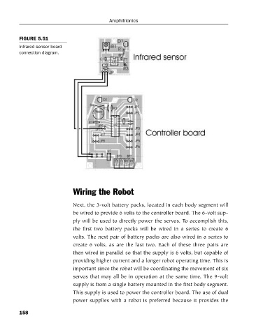
FIGURE 5.51
Infrared sensor board
connection diagram. Amphibionics
Wiring the Robot
Next, the 3-volt battery packs, located in each body segment will
be wired to provide 6 volts to the controller board. The 6-volt sup-
ply will be used to directly power the servos. To accomplish this,
the first two battery packs will be wired in a series to create 6
volts. The next pair of battery packs are also wired in a series to
create 6 volts, as are the last two. Each of these three pairs are
then wired in parallel so that the supply is 6 volts, but capable of
providing higher current and a longer robot operating time. This is
important since the robot will be coordinating the movement of six
servos that may all be in operation at the same time. The 9-volt
supply is from a single battery mounted in the first body segment.
This supply is used to power the controller board. The use of dual
power supplies with a robot is preferred because it provides the
158