
Page 309 - Amphibionics : Build Your Own Biologically Inspired Robot
P. 309
Amphibionics 07 3/24/03 9:13 AM Page 288
Amphibionics
Theory of operation.
The SRF04 works by sending a pulse of
sound outside the range of human hearing. This pulse travels at the
speed of sound (1.1 ft/ms) away from the ranger in a cone shape.
If any objects are in the path of the pulse, the sound is reflected off
the object and back to the ranger. The ranger is paused for a brief
interval after the sound is transmitted and then awaits the reflect-
ed sound in the form of an echo. The controller driving the ranger
requests the device to create a 40-kHz sound pulse, and then waits
for the return echo. If the echo is received, the ranger reports this
echo to the controller, and the controller can then compute the dis-
tance to the object, based on the elapsed time.
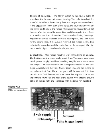
Connections. The ranger requires four connections to operate.
The first two are the power and ground lines. The ranger requires a
5-volt power supply capable of handling roughly 50 mA of continu-
ous output. The other two lines are the signal connections. The first
signal connection is the pulse trigger input line, and the second is
the echo output line. These two pins will be connected to two
input/output (I/O) lines of the microcontroller. Figure 7.14 shows
the connection pins on the back of the device. Note that the ground
pin is on the far right and is marked with the letter “G” beside it.
FIGURE 7.14
SRF04 pin connections.
288