Page 306 - Amphibionics : Build Your Own Biologically Inspired Robot
P. 306

Amphibionics 07  3/24/03  9:13 AM  Page 285
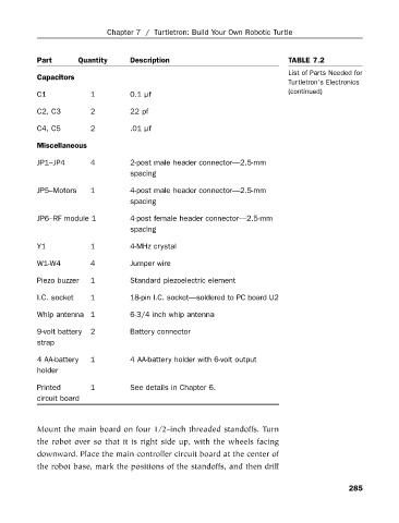
                                                                                   TABLE 7.2
                                              Description
                        Part
                                                                                   List of Parts Needed for
                        Capacitors  Quantity Chapter 7 / Turtletron: Build Your Own Robotic Turtle
                                                                                   Turtletron’s Electronics
                        C1           1        0.1 µf                               (continued)
                        C2, C3       2        22 pf
                        C4, C5       2        .01 µf
                        Miscellaneous
                        JP1–JP4      4        2-post male header connector—2.5-mm
                                              spacing
                        JP5–Motors   1        4-post male header connector—2.5-mm
                                              spacing
                        JP6–RF module 1       4-post female header connector—2.5-mm
                                              spacing
                        Y1           1        4-MHz crystal

                        W1-W4        4        Jumper wire
                        Piezo buzzer  1       Standard piezoelectric element

                        I.C. socket  1        18-pin I.C. socket—soldered to PC board U2
                        Whip antenna 1        6-3/4 inch whip antenna

                        9-volt battery  2     Battery connector
                        strap

                        4 AA-battery   1      4 AA-battery holder with 6-volt output
                        holder

                        Printed      1        See details in Chapter 6.
                        circuit board


                        Mount the main board on four 1/2-inch threaded standoffs. Turn
                        the robot over so that it is right side up, with the wheels facing
                        downward. Place the main controller circuit board at the center of
                        the robot base, mark the positions of the standoffs, and then drill


                                                                                                 285
   301   302   303   304   305   306   307   308   309   310   311