
Page 65 - Amphibionics : Build Your Own Biologically Inspired Robot
P. 65
Amphibionics 03 3/24/03 8:11 AM Page 44
Amphibionics
Testing the Controller Board
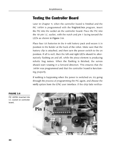
Later in Chapter 4, when the controller board is finished and the
PIC 16F84 is programmed with the frog-test.hex program, insert
the PIC into the socket on the controller board. Place the PIC into
the 18-pin I.C. socket, with the notch and pin 1 facing toward the
LEDs as shown in Figure 3.6.
Place four AA batteries in the 6-volt battery pack and secure it in
position in the holder at the back of the robot. Make sure that the
battery clip is attached, and then turn the power switch to the on
position. If all is well, then the left and right LEDs should be alter-
natively flashing on and off, while the piezo element is producing
robotic frog noises. When the flashing is finished, the servos
should start rotating in a forward direction. This ensures that the
16F84 was programmed and that the controller board is function-
ing properly.
If nothing is happening when the power is switched on, try going
through the process of programming the PIC again, and choose the
verify option from the EPIC user interface. If the chip fails verifica-
FIGURE 3.6
PIC 16F84 inserted into
I.C. socket on controller
board.
44