
Page 95 - Analog Circuit Design Art, Science, and Personalities
P. 95
The Story of the P2
capacitors could be added. To improve the temperature coefficent of Vas, for
example, you could install a thermistor from the wiper of the 50 k pot over to
one side or the other.
Unlike the P7, the P2 had a lot of AC roll-off, provided by the 15 millihenry
inductor and the 0.47 pF capacitor. It rolled the DC gain off at a steep 10 dB-
per-octave rate down to about 15 kcps and then there was a lead (selected re-
sistor in series with the 0.47 pF) so it could cross over at a unity gain frequency
of about 75 kcps at about 6 or 7 dB per octave. The frequency response was
trimmed and fitted on each individual unit.
However, it is fair to note that the roll-off did not use any Miller integrator
around the output transistor. Consequently, the high-frequency open-loop
output impedance of the P2 was not a whole lot lower than 3 kln. If you com-
bine that statement with the fact that the P2’s input capacitance is just about 600
pF, you can see that the output impedance, just trying to drive the input capaci-
tance, gives you an extra phase shift of about 40 degrees. No wonder each unit
was hand-fitted for response!
The demodulator (46) would put out a voltage right near the +15-V bus if you
did not feed in any amplitude from the AC amplifiers, and then the DC transistor
(47) would not turn on. To get the output transistor on, you had to have a min-
imum amount (perhaps 400 mV p-p) of 5 Mcps signal coming through. And it
was the interaction of that signal that talked back from one board to the other
and let the gain come “into mode.” Look at the coupling capacitor from the
fourth AC amplifier into the demodulator! The P7 had a reasonable value-500
pF. But Bob Malter found something magic about the 7.5 pF, probably because
it was the right way to get the amplifier into “mode.” Surely, Bob Malter was the
embodiment of “The Lightning Empiricist.”
Comments on Rustrak data
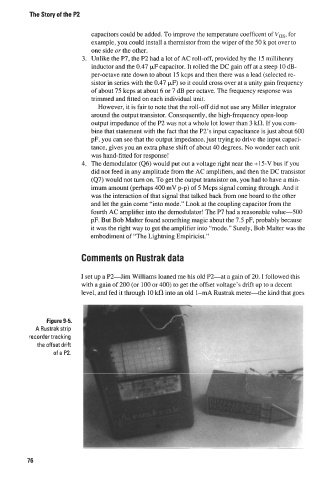
I set up a P2-Jim Williams loaned me his old P2-at a gain of 20. I followed this
with a gain of 200 (or 100 or 400) to get the offset voltage’s drift up to a decent
level, and fed it through 10 klR into an old 1-mA Rustrak meter-the kind that goes
Figure 9-5.
A Rustrak strip
recorder tracking
the offset drift
of a P2.
76