
Page 112 - Analog and Digital Filter Design
P. 112
Poles and Zeroes 1 09
Inverse Chebyshev Pole and Zero locations
As suggested by their name, Inverse Chebyshev filters are derived from
Chebyshev filters. The pole positions are the inverse of those given for
Chebyshev filters. The frequency response of Chebyshev filters was described in
Chapter 2. There are ripples in the passband with a smoothly decaying response
in the stopband. Inverting the pole positions produces a filter with a smooth
passband. The zeroes produce ripple in the stopband. Equations for finding
Inverse Chebyshev poles are given in the Appendix.
Inverse Chebyshev Zero locations
The zero frequency locations for any order of Inverse Chebyshev filter are pro-
vided in equations in the Appendix. Inverse Chebyshev zero locations found
using these equations should be used with pole locations for the natural (nor-
malized to stopband) response. The Inverse Chebyshev response can be normal-
ized to have 3 dB passband attenuation. The zero locations for this response can
be found by modifying these values. I have shown that the poles move away from
the origin by a frequency-scaling factor (see Appendix for more details).
This same frequency factor has to be applied to zeroes, too. The zero locations
move away from the origin, so the whole pole-zero diagram is scaled equally.
Tables 3.16, 3.18, and 3.20 give the scaling factor and the new zero locations
for Inverse Chebyshev filters with a 3dB passband and with 20dB, 30dB, and
40dB stopband attenuation, respectively. Tables 3.15, 3.17, and 3.19 give the
corresponding pole locations.
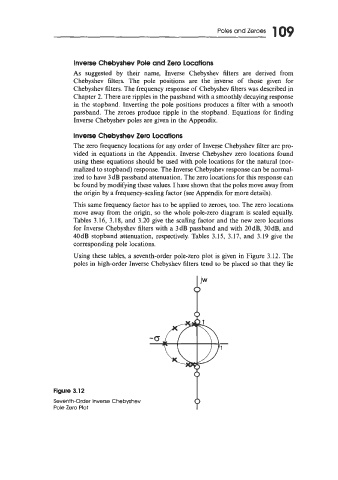
Using these tables, a seventh-order pole-zero plot is given in Figure 3.12. The
poles in high-order Inverse Chebyshev filters tend to be placed so that they lie
Figure 3.12
Seventh-Order Inverse Chebyshev
Pole Zero Plot