
Page 284 - Analog and Digital Filter Design
P. 284
Phase-Shift Networks (All-Pass Filters) 28 1
?
angle = u * temp3;
snn = sin(angle1 ;
cnn = cos(angle1 ;
if (snncO.0)
{
templ = cnnisnn;
temp3 = templ * temp3;
templ = 1.0;
for(j=max-array; j<=0; j-I
{
temp2 = arrayl[jl;
templ = templ * tsmp3;
temp? = temp3 * temp4;
temp4 = (array2 [ j I + templ I (tempZ+templ ;
I
templ = temp3 1 tsmp2 ;
?
snn = l.Orsqrt(temp3*temp3+1.0I;
cnn = temp3 * snn;
?
sn = snn;
cn = cnn;
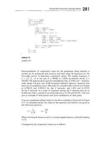
Listing 9.2
H/LB€RT. CP P
Denormalization of component values for the quadrature phase network is
carried out by scaling the pole location and then using the equations for the
first-order section to determine component values. The scaling frequency is
fu = dm, so in the case of a 300Hz to 3.4kHz quadrature circuit, J;J =
10IOHz. The pole locations must be multiplied by 2~o, 6346 rads-'. A fourth-
or
order design will give over 38 dB unwanted sideband rejection, assuming that
there are no amplitude errors. The poles for a fourth-order network are located
at 6.790134 and 0.590319 for the P network, and 1.694 and 0.147272
for the N network. As a result of frequency scaling, the P network poles are at
43,090 and 3746.2, and the N network poles are at 10,750 and 934.59. I will now
give an example of both passive and active realizations of these poles.
A passive quadrature design based on the above example is illustrated in Figure
9.17. As described earlier, the values of the capacitor and inductor are given by
the following equations:
2R
c=- L=-
2
G.R G
Where cis the pole location and L is a center tapped inductor, each half-winding
= Ll4.
Consequently the component values are as follows: