
Page 315 - Analog and Digital Filter Design
P. 315
3 1 2 Analog and Digital Filter Design
[:I
wC = Yo tan - = Yo, where r, is the characteristic admittance of the
open-circuit line.
gz = 1.436 = 50 x WC = 50 x Y,,, where w = 27c x lo8, the passband edge.
1.436 50
=
Y, =- or preferably 2, = - 34.82 Q. The final circuit is shown
50 1.436
in Figure 12.1.
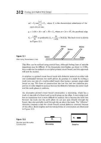
82ohm 82ohm
Figure 12.1
Filter Using Transmission Lines
This iilter can be realized using coaxial lines, although finding lines of suitable
impedance may be difficult. If the frequencies were higher, say closer to 1 GHz,
they could also be realized as a stripline printed circuit board, and this approach
will now be studied.
A stripline is a printed circuit board track with dielectric material on either side
and sandwiched between two earth planes. In practice it is made by etching a
track onto one side of a double-sided board, then laying a second, single-sided
board on top. This form of construction has low loss and low radiation pro-
perties; it is also simple to analyze because the dielectric between the center track
and the earth planes is uniform.
An alternative printed circuit board construction is microstrip, which has a
track on one side of a board and an earth plane on the other. A microstrip track
has an impedance that is more difficult to analyze; this is because the field lines
between the track and the earth plane do not just pass directly through the
board, they also partially travel through the air above the track. The “effective”
dielectric constant is less the circuit board’s actual dielectric constant because
of this effect. Both stripline and microstrip forms of construction are illustrated
in Figure 12.2.
Figure 12.2
Stripline and Microstrip
Construction Microstrip Stripline