
Page 316 - Analog and Digital Filter Design
P. 316
Transmission Lines and Printed Circuit Eoards as Filters 3
Suppose you wish to design a stripline filter. The problem is that the short-
circuited line would be very difficult to produce on a printed circuit board. It
would be necessary to use a coplanar line (two parallel lines) between the earth
planes. An alternative option is to transform the short-circuited line into an
L structure, comprising an open-circuit line and a series section, Kuroda's
identity (see rcference 3) gives the relationship between the two structures and
equations have been presented here to simplify the conversion.
The open circuit line impedance is given by the equation:
2"
Z' = Z, +-, where 2 is the value of the short-circuit line impedance
2
and Z' is the replacement open-circuit line value. Z, is the filter's
source and load impedance, that is, 50Q.
Z'= 50 + 31.25 = 81.25Q.
The series section line impedance Z,' is given by the equation: 2,' = Z,
+ 2, where 2 is the value of the short-circuit line impedance and 2'
is the series section line impedance. As before, Z,, is the filter's source
and load impedance. 2,' = 50 + 81.625 = 131.625Q.
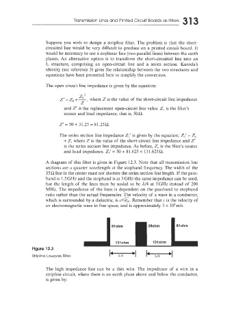
A diagram of this filter is given in Figure 12.3. Note that all transmission line
sections are a quarter wavelength at the stopband frequency. The width of the
35Q line in the center must not shorten the series section line length. If the pass-
band is I .5 GHz and the stopband is at 3 GHz the same impedance can be used,
but the length of the lines must be scaled to be d/4 at 3GHz instead of 200
MHz. The impedance of the lines is dependent on the passband to stopband
ratio rather than the actual frequencies. The velocity of a wave in a conductor,
which is surrounded by a dielectric, is r/&. Remember that c is the velocity of
an electromagnetic wave in free space, and is approximately 3 x 10⁸m/s.
Figure 12.3 111
Slohm
35ohm
Slohm
Stripline Lowpass Filter l3lohm I3lohm
The high impedance line can be a thin wire. The impedance of a wire in a
stripline circuit, where there is an earth plane above and below the conductor,
is given by: