
Page 341 - Analog and Digital Filter Design
P. 341
338 Analog and Digital Filter Design
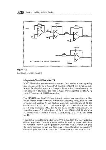
Figure 14.2
Part Circuit of MAX274/MAX275
Integrated Circuit Filter MAX275
MAX275 contains two second-order sections. Each section is made up using
four op-amps, as shown in Figure 14.2. Like the MAX274, this device can only
be used for all-pole lowpass and bandpass filters, unless external op-amp cir-
cuits are added. This device can work at higher frequencies than the MAX274;
a cutoff frequency of 300 kHz is possible.
The MAX274 and MAX275 have internal resistors and capacitors; a filter
can be created by the addition of four external frequency setting resistors. Two
of the internal resistors, R1 and R2, have a selectable ratio; the ratio of R2: R1
can be either 1 :4, 5: 1, or 25: 1. With control pin FC connected to V' the ratio
is 1 : 4 using nominally 13 KQ for R2 and 52 kQ for R1. Connecting FC to
ground produces a 5 : 1 ratio using 65 kQ for R2 and 13 kC2 for R1. Finally, with
FC connected to V- the ratio of R2 : R1 is 25 : 1, using 325 kC2 for R2 and 13 kC2
€or R1.
The internal capacitors have a low value (79.5pF) and low-frequency poles are
difficult to produce. The only practical method for working below 100Hz is to
use a resistor T circuit; this is a potential divider and a series resistor that gives
the equivalent input current as a high-value resistor. Details of the resistor T
circuit are given in the MAX274/MAX275 data sheet available from Maxim.