Page 169 - Analysis and Design of Energy Geostructures
P. 169

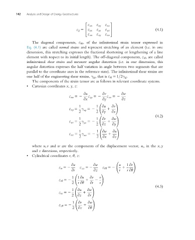
142   Analysis and Design of Energy Geostructures


                                                2             3
                                           ε ij 5  4  ε xx  ε xy  ε xz  5              ð4:1Þ
                                                           ε yz
                                                      ε yy
                                                  ε yx
                                                           ε zz
                                                 ε zx
                                                      ε zy
                   The diagonal components, ε kk , of the infinitesimal strain tensor expressed in
                Eq. (4.1) are called normal strains and represent stretching of an element (i.e. in one
                dimension, this stretching expresses the fractional shortening or lengthening of a line
                element with respect to its initial length). The off-diagonal components, ε kl , are called
                infinitesimal shear strains and measure angular distortion (i.e. in one dimension, this
                angular distortion expresses the half variation in angle between two segments that are
                parallel to the coordinate axes in the reference state). The infinitesimal shear strains are
                one half of the engineering shear strains, γ , that is ε kl 5 1=2γ .
                                                     kl               kl
                   The components of the strain tensor are as follows in relevant coordinate systems.
                •  Cartesian coordinates x, y, z:


                                       ε xx 52  @u  ε yy 52  @v  ε zz 52  @w
                                               @x         @y        @z
                                                                 !
                                             1
                                       ε xy 5 γ 52    1 @u  1  @v
                                             2  xy    2 @y     @x
                                                                                       ð4:2Þ
                                                                 !
                                             1
                                       ε yz 5 γ 52    1 @v  1  @w
                                             2  yz    2 @z     @y
                                                                 !
                                             1
                                       ε xz 5 γ 52    1 @w   1  @u
                                             2  xz    2   @x   @z

                   where u; v and w are the components of the displacement vector, u i , in the x; y
                   and z directions, respectively.
                •  Cylindrical coordinates r, θ, z:

                                                                           !
                                  ε rr 52  @u  ε zz 52  @w  ε θθ 52  u  1  1 @v
                                                                       r @θ
                                         @r          @z            r
                                                         !
                                  ε rθ 52  1 1 @u  1  @v  2  v
                                         2  r @θ   @r   r
                                                                                       ð4:3Þ
                                                    !
                                  ε rz 52  1 @u  1  @w
                                         2 @z     @r
                                                    !
                                  ε zθ 52  1 @v  1  @w
                                                  @θ
                                         2 @z
   164   165   166   167   168   169   170   171   172   173   174