
Page 109 - Analysis and Design of Machine Elements
P. 109
Detachable Joints and Fastening Methods
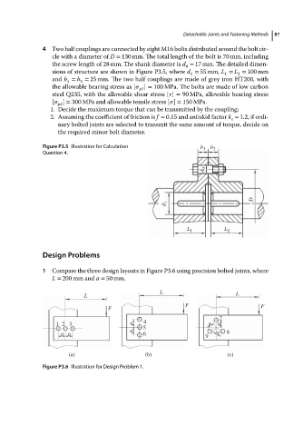
4 Two half couplings are connected by eight M16 bolts distributed around the bolt cir- 87
cle with a diameter of D = 130 mm. The total length of the bolt is 70 mm, including
the screw length of 28 mm. The shank diameter is d = 17 mm. The detailed dimen-
0
sions of structure are shown in Figure P3.5, where d = 55 mm, L = L = 100 mm
1 1 2
and b = b = 25 mm. The two half couplings are made of grey iron HT200, with
1 2
theallowablebearing stress as [ ] = 100 MPa. The bolts are made of low carbon
p1
steel Q235, with the allowable shear stress [ ] = 90 MPa, allowable bearing stress
[ ] = 300 MPa and allowable tensile stress [ ] = 150 MPa.
p2
1. Decide the maximum torque that can be transmitted by the coupling;
2. Assuming the coefficient of friction is f = 0.15 and antiskid factor k = 1.2, if ordi-
s
nary bolted joints are selected to transmit the same amount of torque, decide on
the required minor bolt diameter.
Figure P3.5 Illustration for Calculation b 1 b 2
Question 4.
d 0
D
d 1
L 1 L 2
Design Problems
1 Compare the three design layouts in Figure P3.6 using precision bolted joints, where
L = 200 mm and a = 50 mm.
L
L L
F F
F
7
12 3 aa 5 4 a a
aa 6 9 a 8
(a) (b) (c)
Figure P3.6 Illustration for Design Problem 1.