
Page 114 - Analysis and Design of Machine Elements
P. 114
Analysis and Design of Machine Elements
92
Keys are elements enabling transmission of torque and power between power trans-
mitting elements and shafts. A key is first installed into longitudinal groove cut into a
shaft, called a keyseat. The hub of a power transmitting element with a similar groove,
usually called a keyway or a keyseat, is then slid over the key. The key seats in the groove
of the shaft and the hub so that exactly half the height of the key bears on the shaft
and the other half bears on the hub [1]. Keys are demountable, facilitating assembly and
disassembly of a shaft system.
4.1.2 Types of Keys
Several types of keys are available, including parallel keys, Woodruff keys, taper keys
andgib-headkeys. Parallelkeysare namedbecause thetop,bottomand thesidesofkey
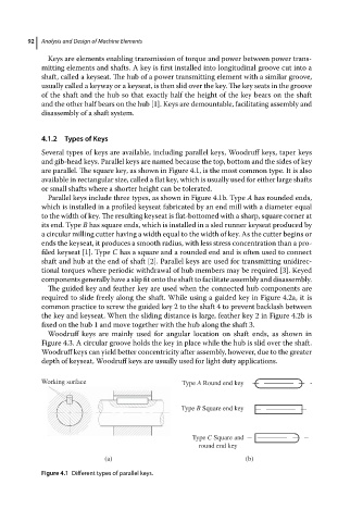
are parallel. The square key, as shown in Figure 4.1, is the most common type. It is also
available in rectangular size, called a flat key, which is usually used for either large shafts
or small shafts where a shorter height can be tolerated.
Parallel keys include three types, as shown in Figure 4.1b. Type A has rounded ends,
which is installed in a profiled keyseat fabricated by an end mill with a diameter equal
to the width of key. The resulting keyseat is flat-bottomed with a sharp, square corner at
its end. Type B has square ends, which is installed in a sled runner keyseat produced by
a circular milling cutter having a width equal to the width of key. As the cutter begins or
ends the keyseat, it produces a smooth radius, with less stress concentration than a pro-
filed keyseat [1]. Type C has a square and a rounded end and is often used to connect
shaft and hub at the end of shaft [2]. Parallel keys are used for transmitting unidirec-
tional torques where periodic withdrawal of hub members may be required [3]. Keyed
components generally have a slip fit onto the shaft to facilitate assembly and disassembly.
The guided key and feather key are used when the connected hub components are
required to slide freely along the shaft. While using a guided key in Figure 4.2a, it is
common practice to screw the guided key 2 to the shaft 4 to prevent backlash between
the key and keyseat. When the sliding distance is large, feather key 2 in Figure 4.2b is
fixed on the hub 1 and move together with the hub along the shaft 3.
Woodruff keys are mainly used for angular location on shaft ends, as shown in
Figure 4.3. A circular groove holds the key in place while the hub is slid over the shaft.
Woodruff keys can yield better concentricity after assembly, however, due to the greater
depth of keyseat, Woodruff keys are usually used for light duty applications.
Working surface Type A Round end key
Type B Square end key
Type C Square and
round end key
(a) (b)
Figure 4.1 Different types of parallel keys.