
Page 119 - Analysis and Design of Machine Elements
P. 119
(a) (b) Detachable Fastenings for Shaft and Hub 97
(c)
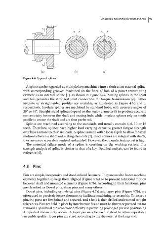
Figure 4.6 Types of splines.
A spline can be regarded as multiple keys machined into a shaft as an external spline,
with corresponding grooves machined on the bore of hub of a power transmitting
element as an internal spline [1], as shown in Figure 4.6a. Mating splines in the shaft
and hub provides the strongest joint connection for torque transmission [6]. Either
involute or straight-sided profiles are available, as illustrated in Figure 4.6b and c,
respectively. Involute splines are machined by standard hobs, with pressure angles of
∘
∘
30 or 45 . Straight-sided splines depend on the major diameter fit to produce accurate
concentricity between the shaft and mating hub; while involute splines rely on tooth
profile to centre the shaft and are thus preferred.
Splines are machined according to the standards and usually contain 4, 6, 10 or 16
teeth. Therefore, splines have higher load carrying capacity, greater fatigue strength
over keys as more teeth share loads. A spline is made with a loose slip fit to allow for axial
motion between a shaft and mating elements [7]. Since splines are integral with shafts,
they are more accurately centred and guided. However, the manufacturing cost is high.
The potential failure mode of a spline is crushing on the working surface. The
strength analysis of spline is similar to that of a key. Detailed analysis can be found in
reference [5].
4.3 Pins
Pins are simple, inexpensive and standardized fasteners. They are used to fasten machine
elements together, to keep them aligned (Figure 4.7a) or to prevent rotational motion
between shaft and mounted elements (Figure 4.7b). According to their functions, pins
are classified as Dowel pins, shear pins and many others.
Dowel pins, including cylindrical pins (Figure 4.7a) and taper pins (Figure 4.7b), are
often used to precisely locate elements to facilitate machining or assembly. To insert a
pin, the parts are first joined and secured, and a hole is then drilled and reamed to tight
tolerances. Pins are held in place by interference fit and must be driven or pressed out for
removal. Cylindrical pins confront difficulty in providing prolonged precise positioning
if repeated disassembly occurs. A taper pin may be used instead to attain repeatable
assembly quality. Taper pins are sized according to the diameter at the large end.