
Page 122 - Analysis and Design of Machine Elements
P. 122
Analysis and Design of Machine Elements
100
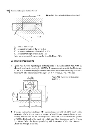
b Hub Figure P4.2 Illustration for Objective Question 5.
k
a F
h
F a
d T Shaft
O
(a) install a pair of keys
(b) increase the width of the key to 1.5b
(c) increase the diameter of the shaft to 1.5d
(d) increase the height of the key to 1.5h
Note: parameters of d, b and h can be found in Figure P4.2.
Calculation Questions
1 Figure P4.3 shows a rigid flanged coupling made of medium carbon steel, with an
allowable bearing stress of [ ] = 100 MPa. The maximum transmitted stable torque
p
is 1200 N m. Select the key type, determine the main dimensions of the key and check
its strength. The dimensions in the figure are d = 55 mm, L = L = 84 mm.
2
1
1
b b Figure P4.3 Illustration for Calculation
1 2
Question 1.
D
d 1
L L
1 2
2 The cone clutch shown in Figure P4.4 transmits a power of P = 2.5 kW. Shaft 4 with
adiameterof d = 52 mm rotates at a speed of n = 250 rpm, subjected to an impact
loading. The material for the coupling is cast steel, with an allowable bearing stress
as 75 MPa. The length of the hub 3 is L = 120 mm. Other dimensions are S = 10 mm,
1
L = 40 mm. Select the Type A parallel key with dimensions of 16 × 10 × 140 mm.
2
Check the strength of the key.