
Page 117 - Analysis and Design of Machine Elements
P. 117
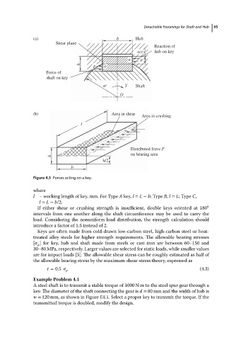
(a)                               b       Hub  Detachable Fastenings for Shaft and Hub  95
                                   Shear plane
                                                                           Reaction of
                                                                      h  2  hub on key
                                                                 a    F
                                             h
                                                  F    a
                               Force of
                               shaft on key
                                                      d        T    Shaft
                                                             O


                          (b)                             Area in shear
                                                                      Area in crushing
                                             l


                                                                  Distributed force F
                                                                  on bearing area
                                 h
                                                      h/2
                                         b
                          Figure 4.5 Forces acting on a key.

                          where
                          l – working length of key, mm. For Type A key, l = L − b;Type B, l = L;Type C,
                            l = L − b/2.
                            If either shear or crushing strength is insufficient, double keys oriented at 180 ∘
                          intervals from one another along the shaft circumference may be used to carry the
                          load. Considering the nonuniform load distribution, the strength calculation should
                          introduce a factor of 1.5 instead of 2.
                            Keys are often made from cold-drawn low-carbon steel, high-carbon steel or heat-
                          treated alloy steels for higher strength requirements. The allowable bearing stresses
                          [   ] for key, hub and shaft made from steels or cast iron are between 60–150 and
                            p
                          30–80 MPa, respectively. Larger values are selected for static loads, while smaller values
                          are for impact loads [5]. The allowable shear stress can be roughly estimated as half of
                          the allowable bearing stress by the maximum-shear-stress theory, expressed as
                                  = 0.5                                                       (4.3)
                                       p
                          Example Problem 4.1
                          A steel shaft is to transmit a stable torque of 1000 N m to the steel spur gear through a
                          key. The diameter of the shaft connecting the gear is d = 80 mm and the width of hub is
                          w = 120 mm, as shown in Figure E4.1. Select a proper key to transmit the torque. If the
                          transmitted torque is doubled, modify the design.