
Page 116 - Analysis and Design of Machine Elements
P. 116
94
Analysis and Design of Machine Elements
When taper keys, including gib-head keys in Figure 4.4b, are installed in place, they
are normally driven tightly and rely on the top and bottom working surfaces to transmit
torque and power. In contrast to parallel keys, there is clearance on both sides. When
overload or the shaft and hub move relative to each other, the side surface can work like
parallel keys to transmit torque. Therefore, taper keys work for heavy duty service to
transmit unidirectional, reversing or vibrating torques and in applications where peri-
odic withdrawal of the key may be necessary [3].
Taper keys are used in pairs to transmit heavy unidirectional torques. Two pairs of
∘
taper keys arranged at 120 interval are used to transmit bidirectional torques. Because
of the eccentricity caused by taper keys, they are best suited for large diameter shafts
where the adverse effect of eccentricity can be neglected.
4.1.3 Strength Analysis
The size of key for a particular application is usually selected after the shaft diameter has
been specified. The standard sizes for width and height, as functions of shaft diameter,
are listed in abridged form in Table 4.1. The length of key is selected according to the
hub width and the torsional load to be transmitted. Keys normally extend along the full
width of hub and, for good stability, hub widths are commonly 1.5d to 2d,where d is the
diameter of mating shaft.
Keys are used as detachable fasteners for the connection of shafts and hubs and are
subjected to shearing and compressive bearing stresses. Therefore, potential failures for
keys include shearing across the shaft and hub interface and crushing failure due to
bearing stress between the sides of key and the shaft or hub.
Figure 4.5 shows that a torque in the shaft creates a force on the lower left side of the
key. The key in turn exerts a force on the right side of the hub keyseat. The reaction force
of the hub react back on the upper right side of the key. These forces on the key directly
shears the key over its cross section. The force is commonly assumed to be uniformly
distributed over the surfaces and is the quotient of torque and shaft radius. To ensure
safety, the shear stress must satisfy,
2T
= ≤ [ ] (4.1)
bld
The failure in crushing is related to the compressive stress on the side of key, the side
of shaftkeyseat or theside of hubkeyseat;whichever is theweakest.Theareainthe
bearing is the same for either of these zones, expressed as l × h/2. Failure occurs on the
surface with the lowest allowable stress. The crushing strength is
4T
= ≤ [ ] (4.2)
p
p
hld
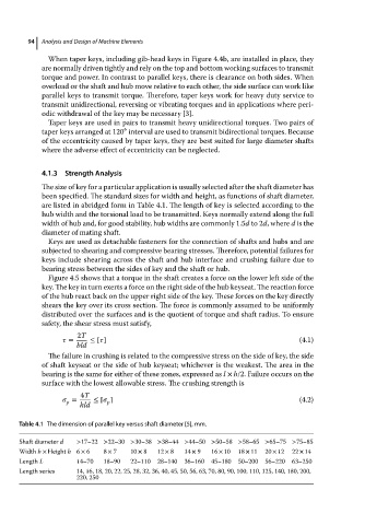
Table 4.1 The dimension of parallel key versus shaft diameter [5], mm.
Shaft diameter d >17–22 >22–30 >30–38 >38–44 >44–50 >50–58 >58–65 >65–75 >75–85
Width b × Height h 6 × 6 8 × 7 10 × 8 12 × 8 14 × 9 16 × 10 18 × 11 20 × 12 22 × 14
Length L 14–70 18–90 22–110 28–140 36–160 45–180 50–200 56–220 63–250
Length series 14, 16, 18, 20, 22, 25, 28, 32, 36, 40, 45, 50, 56, 63, 70, 80, 90, 100, 110, 125, 140, 180, 200,
220, 250