
Page 118 - Analysis and Design of Machine Elements
P. 118
Analysis and Design of Machine Elements
96
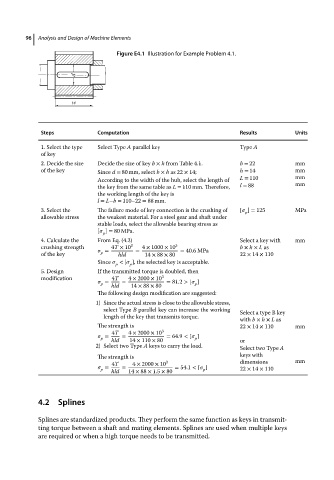
Figure E4.1 Illustration for Example Problem 4.1.
Steps Computation Results Units
1. Select the type Select Type A parallel key Type A
of key
2. Decide the size Decide the size of key b × h from Table 4.1. b = 22 mm
of the key Since d = 80 mm, select b × h as 22 × 14; h = 14 mm
According to the width of the hub, select the length of L = 110 mm
the key from the same table as L = 110 mm. Therefore, l = 88 mm
the working length of the key is
l = L−b = 110–22 = 88 mm.
3. Select the The failure mode of key connection is the crushing of [ ] = 125 MPa
p
allowable stress the weakest material. For a steel gear and shaft under
stable loads, select the allowable bearing stress as
[ ] = 80 MPa.
p
4. Calculate the From Eq. (4.2) Select a key with mm
crushing strength = 4T × 10 3 = 4 × 1000 × 10 3 = 40.6 MPa b × h × L as
of the key p hld 14 × 88 × 80 22 × 14 × 110
Since < [ ], the selected key is acceptable.
p
p
5. Design If the transmitted torque is doubled, then
modification 4T 4 × 2000 × 10 3
= = = 81.2 > [ ]
p
p
hld 14 × 88 × 80
The following design modification are suggested:
1) Since the actual stress is close to the allowable stress,
select Type B parallel key can increase the working Select a type B key
length of the key that transmits torque.
with b × h × L as
The strength is 22 × 14 × 110 mm
4T 4 × 2000 × 10 3
= = = 64.9 < [ ]
p hld 14 × 110 × 80 p or
2) Select two Type A keys to carry the load. Select two Type A
The strength is keys with
4T 4 × 2000 × 10 3 dimensions mm
= = = 54.1 < [ ]
p hld 14 × 88 × 1.5 × 80 p 22 × 14 × 110
4.2 Splines
Splines are standardized products. They perform the same function as keys in transmit-
ting torque between a shaft and mating elements. Splines are used when multiple keys
are required or when a high torque needs to be transmitted.