
Page 184 - Analysis and Design of Machine Elements
P. 184
Analysis and Design of Machine Elements
162
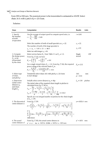
from 230 to 240 rpm. The nominal power to be transmitted is estimated as 10 kW. Select
chain 16 A with a pitch of p = 25.4 mm.
Solution
Steps Computation Results Units
1. Specify Use the average of output speed to compute speed ratio, i.e. i = 3.83
the number i = n 1 = 900 = 3.83
of teeth n 2 235
of sprockets
Select the number of teeth of small sprocket as z = 21 z = 21
1
1
The number of teeth of the large sprocket is
z = iz =3.83 × 21 = 80.4 z = 81
2
2 1
Select an odd integer z = 81
2
2. Compute Select service factor K from Table 2.1 as K = 1.5. Single kW
A
A
the design power From Eq. (7.22), we have strand
P to be ( 19 ) 1.08 ( 19 ) 1.08
ca
transmitted K = = = 0.9
z
by the chain z 1 21
For a single-strand chain, K = 1.0. From Eq. (7.24), the required P = 13.5
p
0
power rating of the selected chain P is
0
K K P 1.5 × 0.9 × 10
P = A z = = 13.5
0 K p 1.0
3. Select type Tentatively select chain 16A with pitch p = 25.4 mm 16A mm
of chain, to start design p = 25.4
and pitch p
4. Determine Initially select centre distance a = 40p. L = 134 pitches
p
0
initial centre The initial value of the required chain length in pitches is
distance a 0 calculated from Eq. (7.28) as
and chain 2a 0 z + z 2 ( z − z 1 ) 2 p
2
1
length L p L p0 = p + 2 + 2 a
0
2 × 40p 21 + 81 ( 81 − 21 ) 2 p
L = + + = 133.3
p0 p 2 2 40p
Specify an even integral number of pitches for the chain length
as L = 134.
p
5. The theoretical From Eq. (7.29) a = 1025.4 mm
√
centre distance a ⎡ ( ) ( ) 2
p z + z 2 z + z 2 ( z − z 1 ) 2 ⎤
1
2
1
a = ⎢ L − + L − − 8 ⎥
p
p
4 ⎢ 2 2 2 ⎥
⎣ ⎦
a = [ ]
√
p ( 21 + 81 ) ( 21 + 81 ) 2 ( 81 − 21 ) 2
134 − + 134 − − 8 =
4 2 2 2
1025.4mm
′
6. The actual From Eq. (7.30), the actual centre distance is a = 1021 mm
centre distance a ′ a = a −Δa = 1025.4 - 0.004 × 1025.4 ≈ 1021mm
′