
Page 190 - Analysis and Design of Machine Elements
P. 190
Analysis and Design of Machine Elements
168
4 A rock crusher is driven by a 75 kW hydraulic drive at a speed of 625 rpm. The rock
crusher is to operate at 225 rpm, subject to heavy service. A centre distance of from
1000 to 1500 mm will be acceptable. Design a roller chain drive.
Structure Design Problems
1 In the design of chain sprocket, the number of teeth of driving and driven sprockets
are limited by z = 9and z = 120, respectively. Explain the reason.
min max
2 In chain design, why the speed ratio has a limitation of less than 8?
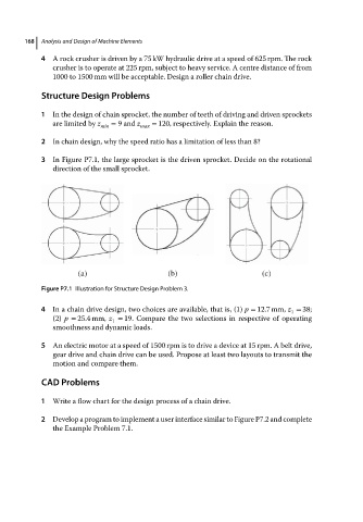
3 In Figure P7.1, the large sprocket is the driven sprocket. Decide on the rotational
direction of the small sprocket.
(a) (b) (c)
Figure P7.1 Illustration for Structure Design Problem 3.
4 In a chain drive design, two choices are available, that is, (1) p = 12.7 mm, z = 38;
1
(2) p = 25.4 mm, z = 19. Compare the two selections in respective of operating
1
smoothness and dynamic loads.
5 An electric motor at a speed of 1500 rpm is to drive a device at 15 rpm. A belt drive,
gear drive and chain drive can be used. Propose at least two layouts to transmit the
motion and compare them.
CAD Problems
1 Write a flow chart for the design process of a chain drive.
2 Develop a program to implement a user interface similar to Figure P7.2 and complete
the Example Problem 7.1.