
Page 251 - Analysis and Design of Machine Elements
P. 251
a) the allowable output torque T output Gear Drives 229
by contact strength calculation;
b) if after heat treatment, the allowable stresses of the pinions increase to
′
′
[ ] = [ ] = 650 MPaand theallowablestressesofthe gearsincreaseto
H3
H1
′
′
[ ] = [ ] = 600 MPa, by what percentage will the allowable output torque
H2 H4
T calculated by contact strength analysis be increased by?
output
Design Problems
1 The input power for a pair of helical gears is P = 5.5 kW. The pinion and gear rotate
1
at n = 480 rpm and n = 150 rpm, respectively. The initially selected variables are:
1 2
∘
the number of teeth of the pinion z = 28, helix angle = 12 , face width ratio
1
= 1.1. The calculated pitch diameter by tooth surface fatigue strength analysis is
d
d = 70.13 mm. Decide the normal module m , centre distance a,helix angle and
1 n
face width of the pinion b and gear b .
1 2
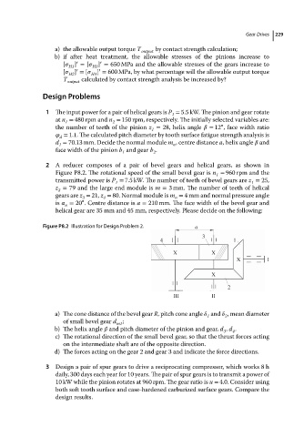
2 A reducer composes of a pair of bevel gears and helical gears, as shown in
Figure P8.2. The rotational speed of the small bevel gear is n = 960 rpm and the
1
transmitted power is P = 7.5 kW. The number of teeth of bevel gears are z = 25,
1
1
z = 79 and the large end module is m = 3 mm. The number of teeth of helical
2
gears are z = 21, z = 80. Normal module is m = 4 mm and normal pressure angle
3
n
4
∘
is = 20 . Centre distance is a = 210 mm. The face width of the bevel gear and
n
helical gear are 35 mm and 45 mm, respectively. Please decide on the following:
Figure P8.2 Illustration for Design Problem 2. a
3
4 1
X X
X I
X
2
III II
a) The cone distance of the bevel gear R, pitch cone angle and ,meandiameter
1 2
of small bevel gear d ;
m1
b) The helix angle and pitch diameter of the pinion and gear, d , d .
4
3
c) The rotational direction of the small bevel gear, so that the thrust forces acting
on the intermediate shaft are of the opposite direction.
d) The forces acting on the gear 2 and gear 3 and indicate the force directions.
3 Design a pair of spur gears to drive a reciprocating compressor, which works 8 h
daily, 300 days each year for 10 years. The pair of spur gears is to transmit a power of
10 kW while the pinion rotates at 960 rpm. The gear ratio is u = 4.0. Consider using
both soft tooth surface and case-hardened carburized surface gears. Compare the
design results.