
Page 246 - Analysis and Design of Machine Elements
P. 246
Analysis and Design of Machine Elements
224
Table 8.8 Comparison of design results.
Helical gears Helical gears
Spur gears (soft tooth surface) (hard tooth surface)
Variables Example Problem 6.1 Example Problem 6.2 Example Problem 6.3
z /z 104/26 76/19 76/19
2 1
m (m ) 2.5 3 2
n
d 65 57.99 39.999
1
d 260 231.99 159.996
2
a 162.5 145 100
b /b 1 65/70 58/63 40/45
2
0 10.65 ∘ 18.19 ∘
The design results of three cases are summarized in Table 8.8 for comparison. For the
same design task using helical gears, especially hard tooth surface helical gears, one can
obtain a more compact design than using spur gears or soft tooth surface helical gears.
8.7 Structural Design of Gears
The selection of gear structure is relevant to many factors, such as geometrical dimen-
sions, materials, manufacturing methods and costs. The most important factor is diam-
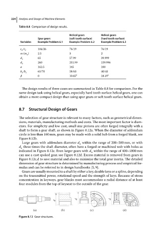
eters. For simplicity and low cost, small size pinions are often forged integrally with a
shaft to form a gear shaft, as shown in Figure 8.12a. When the diameter of addendum
circle is less than 160 mm, gears may be made with a solid hub from a forged blank, see
Figure 8.12b.
Large gears with addendum diameter d within the range of 200–500 mm, or with
a
d three times the shaft diameter, often have a forged or machined web with holes as
a
indicated in Figure 8.12c. Even larger gears with d within the range of 400–1000 mm
a
can use a cast spoked gear, see Figure 8.12d. Excess material is removed from gears in
Figure 8.12c,d to save material and also to minimize the total gear inertia. The detailed
dimension of gear structure is determined by manufacturing process and empirical for-
mulas and can be referred to in design handbooks [5, 9].
Gears are usually mounted to a shaft by either a key, double keys or a spline, depending
on the transmitted power, rotational speed and the strength of keys. Because of stress
concentration in keyways, gear blanks must accommodate a radial distance of at least
four modules from the top of keyseat to the outside of the gear.
d d
d
(a) (b) (c) (d)
Figure 8.12 Gear structures.