
Page 244 - Analysis and Design of Machine Elements
P. 244
Analysis and Design of Machine Elements
222
Steps Computation Results Units
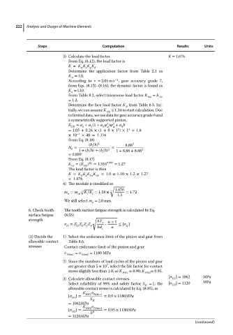
3) Calculate the load factor. K = 1.676
From Eq. (8.12), the load factor is
K = K K K K
A
v
Determine the application factor from Table 2.1 as
K = 1.0.
A
−1
According to v = 2.01 m s , gear accuracy grade 7,
from Eqs. (8.13)–(8.16), the dynamic factor is found as
K = l.10.
v
From Table 8.2, select transverse load factor K Ha = K Fa
= 1.2.
Determine the face load factor K from Table 8.3. Ini-
tially, we can assume K ≤ 1.34 to start calculation. Due
H
to limited data, we use data for gear accuracy grade 6 and
a symmetrically supported pinion,
2
2
K = a + a (1 + a ) + a b
H 1 2 3 d d 4
2
2
=1.05 + 0.26 × (1 + 0 × 1 )×1 +1.6
×10 −4 ×40 = 1.316
From Eq. (8.18)
(b∕h) 2 8.88 2
N = =
0
1 +(b∕h)+(b∕h) 2 1 + 8.88 + 8.88 2
= 0.889
From Eq. (8.17)
K =(K ) N 0 = 1.316 0.889 = 1.27
F H
The load factor is then
K = K K K K =1.0×1.10 × 1.2×1.27
A v F F
=1.676
4) The module is modified as
√
√ 3 1.676
m = m nt 3 K∕K = 1.58 × 1.3 = 1.72
t
n
We still select m = 2.0 mm.
n
6. Check tooth The tooth surface fatigue strength is calculated by Eq.
surface fatigue (8.55)
√
strength KF u ± 1
= Z Z Z Z t ⋅ ≤ [ ]
E
H
H
H
bd
1 u
(1) Decide the 1) Select the endurance limit of the pinion and gear from
allowable contact Table 8.6.
stresses Contact endurance limit of the pinion and gear
Hlim1 = Hlim2 = 1180 MPa
2) Since the numbers of load cycles of the pinion and gear
7
are greater than 5 × 10 , select the life factor for contact
stress slightly less than 1.0, as K = 0.90; K = 0.95.
HN1 HN2
[ ] = 1062 MPa
3) Calculate allowable contact stresses. H1
Select reliability of 99% and safety factor S = 1, the [ ] = 1120 MPa
H H2
allowable contact stress is calculated by Eq. (8.85), as
K HN1 H lim 1
[ ]= = 0.9 × 1180MPa
H1
S H
= 1062MPa
K
[ ]= HN2 H lim 2 = 0.95 × 1180MPa
H2 S H
= 1120MPa
(continued)