
Page 240 - Analysis and Design of Machine Elements
P. 240
Analysis and Design of Machine Elements
218
Steps Computation Results Units
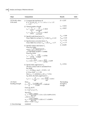
(2) Decide values 1) Compute the load factor K K = 1.537
to be used K = K K K K F =1 × 1.10 × 1.1×1.27
v
A
F
=1.537
z = 20.01
2) Virtual number of teeth v1
z 19 z = 80.07
z = 1 = = 20.01 v2
v1 cos cos 10.65 ∘
3
3
z 76
z = 2 = = 80.07
v2 cos cos 10.65 ∘
3
3
Y = 2.80
3) Specify tooth form factor Y Fa1
Fa
From Table8.4,wehave Y = 2.80; Y = 2.22 Y = 2.22
Fa1 Fa2 Fa2
Y = 1.55
4) Specify stress correction factor Y sa sa1
From Table8.4,wehave Y sa1 = 1.55; Y sa2 = 1.77 Y sa2 = 1.77
Y = 0.699
5) Specify contact ratio factor Y
From Eq. (8.60),
√
cos = 1 −(sin cos ) =
2
n
b
√ ∘
∘ 2
1-(sin 10.65 cos 20 ) = 0.9848
From Eq. (8.59)
1.62
v = = = 1.6704
2
cos b 0.9848 2
From Eq. (8.58)
Y = 0.25 + 0.75 = 0.25 + 0.75 = 0.699
v 1.6704
Y = 0.911
6) Specify helix angle factor Y
The face contact ratio is calculated from
Eq. (8.40)
=0.318 z tan =0.318 × 1.0
d 1
∘
×19 tan 10.65 =1.138
Since > 1, substitute for = 1.0 in
Eq. (8.61), the helix angle factor is
∘
10.65
Y = 1 − ∘ = 1 − 1.0 × ∘ = 0.911
120 120
(3) Check Since The bending
bending strength 2T 1 2 × 9.948 × 10 4 strength is
F = = = 3430.4N
t
d 1 57.999 enough.
From Eq. (8.57)
= KF t Y Y Y Y
F
bm n Fa Sa
Therefore.
1.537 × 3430.4
F1 = 58 × 3.0 × 2.8 × 1.55 × 0.699 × 0.911
= 83.74 < [ ]
F1
1.537 × 3430.4
= × 2.22 × 1.77 × 0.699 ×
F2 58 × 3.0
0.911 = 75.82 < [ ]
F2
6. Gear drawings (omitted)