Page 236 - Analysis and Design of Machine Elements
P. 236

Analysis and Design of Machine Elements
                   214
                        Steps            Computation                            Results         Units
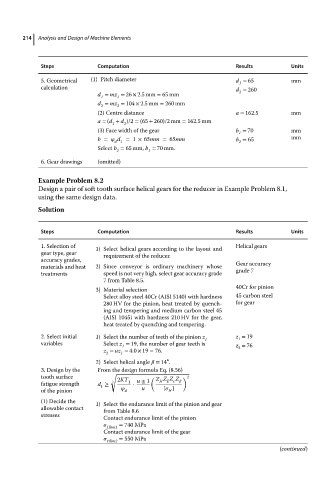
                        5. Geometrical  (1) Pitch diameter                      d = 65          mm
                                                                                 1
                        calculation                                             d = 260
                                         d = mz = 26 × 2.5 mm = 65 mm            2
                                         1
                                              1
                                         d = mz = 104 × 2.5 mm = 260 mm
                                         2    2
                                         (2) Centre distance                    a = 162.5       mm
                                         a = (d + d )/2 = (65 + 260)/2 mm = 162.5 mm
                                             1
                                                2
                                         (3) Face width of the gear             b = 70          mm
                                                                                 1
                                         b =    d =1 × 65mm =65mm               b = 65          mm
                                             d 1
                                                                                 2
                                         Select b = 65 mm, b = 70 mm.
                                              2
                                                       1
                        6. Gear drawings  (omitted)
                       Example Problem 8.2
                       Design a pair of soft tooth surface helical gears for the reducer in Example Problem 8.1,
                       using the same design data.
                       Solution

                        Steps            Computation                            Results         Units

                        1. Selection of  1) Select helical gears according to the layout and  Helical gears
                        gear type, gear   requirement of the reducer.
                        accuracy grades,                                        Gear accuracy
                        materials and heat  2) Since conveyor is ordinary machinery whose  grade 7
                        treatments        speed is not very high, select gear accuracy grade
                                          7 from Table 8.5.
                                                                                40Cr for pinion
                                        3) Material selection
                                          Select alloy steel 40Cr (AISI 5140) with hardness  45 carbon steel
                                          280 HV for the pinion, heat treated by quench-  for gear
                                          ing and tempering and medium carbon steel 45
                                          (AISI 1045) with hardness 210 HV for the gear,
                                          heat treated by quenching and tempering.

                        2. Select initial  1) Select the number of teeth of the pinion z  z = 19
                                                                       1         1
                        variables         Select z = 19, thenumberofgearteeth is
                                                1                               z = 76
                                                                                 2
                                          z = uz = 4.0 × 19 = 76.
                                           2   1
                                                            ∘
                                        2) Select helical angle    = 14 .
                        3. Design by the  From the design formula Eq. (8.56)
                                            √
                        tooth surface        3 2KT  u ± 1  ( Z Z Z Z  )2
                        fatigue strength  d ≥    1  ⋅     H  E        
                                         1           u     [   ]
                        of the pinion           d            H
                        (1) Decide the  1) Select the endurance limit of the pinion and gear
                        allowable contact  from Table 8.6
                        stresses
                                          Contact endurance limit of the pinion
                                             Hlim1  = 740 MPa
                                          Contact endurance limit of the gear
                                             Hlim2  = 550 MPa
                                                                                             (continued)
   231   232   233   234   235   236   237   238   239   240   241