
Page 239 - Analysis and Design of Machine Elements
P. 239
217
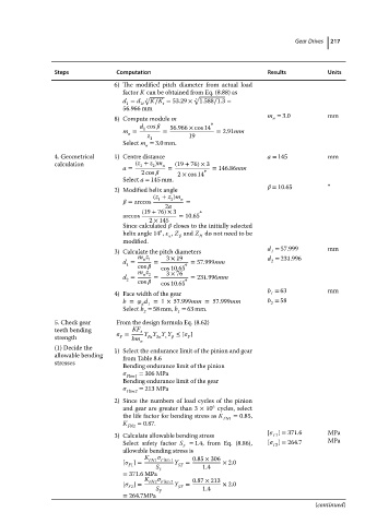
Steps Computation Results Gear Drives Units
6) The modified pitch diameter from actual load
factor K can be obtained from Eq. (8.88) as
√ √
d = d 1t 3 K∕K = 53.29 × 3 1.588∕1.3 =
t
1
56.966 mm
m = 3.0 mm
8) Compute module m n
∘
d cos 56.966 × cos 14
1
m = = = 2.91mm
n
z 1 19
Select m = 3.0 mm.
n
4. Geometrical 1) Centre distance a = 145 mm
calculation (z + z )m n (19 + 76)× 3
1
2
a = = ∘ = 146.86mm
2cos 2 × cos 14
Select a = 145 mm.
= 10.65 ∘
2) Modified helix angle
(z + z )m n
2
1
= arccos =
2a
(19 + 76)× 3 ∘
arccos = 10.65
2 × 145
Since calculated closes to the initially selected
∘
helix angle 14 , , Z and Z do not need to be
H
modified.
d = 57.999 mm
3) Calculate the pitch diameters 1
m z 3 × 19 d = 231.996
d = n 1 = = 57.999mm 2
1
cos cos 10.65 ∘
m z 3 × 76
d = n 2 = ∘ = 231.996mm
2
cos cos 10.65
b = 63 mm
4) Face width of the gear 1
b = d =1 × 57.999mm =57.999mm b = 58
2
d 1
Select b = 58 mm, b = 63 mm.
2
1
5. Check gear From the design formula Eq. (8.62)
teeth bending = KF t Y Y Y Y ≤ [ ]
strength F bm n Fa Sa F
(1) Decide the 1) Select the endurance limit of the pinion and gear
allowable bending from Table 8.6
stresses
Bending endurance limit of the pinion
Flim1 = 306 MPa
Bending endurance limit of the gear
Flim2 = 213 MPa
2) Since the numbers of load cycles of the pinion
6
and gear are greater than 3 × 10 cycles, select
the life factor for bending stress as K FN1 = 0.85,
K FN2 = 0.87.
[ ] = 371.6 MPa
3) Calculate allowable bending stress F1
Select safety factor S = 1.4, from Eq. (8.86), [ ] = 264.7 MPa
F2
F
allowable bending stress is
K 0.85 × 306
[ ]= FN1 F lim 1 Y = × 2.0
F1 S F ST 1.4
= 371.6 MPa
K FN2 F lim 2 0.87 × 213
[ ]= Y ST = × 2.0
F2
S F 1.4
= 264.7MPa
(continued)