
Page 242 - Analysis and Design of Machine Elements
P. 242
Analysis and Design of Machine Elements
220
Steps Computation Results Units
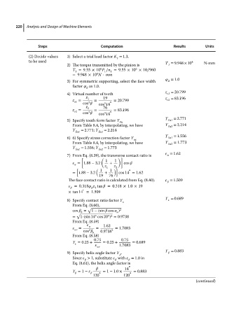
(2) Decide values 1) Select a trial load factor K = 1.3.
t
to be used T = 9.948 × 10 4 N⋅mm
2) The torque transmitted by the pinion is 1
6
6
T =9.55 × 10 P ∕n =9.55 × 10 × 10∕960
1 1 1
4
=9.948 × 10 N ⋅ mm
= 1.0
3) For symmetric supporting, select the face width d
factor as 1.0.
d
z = 20.799
4) Virtual number of teeth v1
z 1 19 z = 83.196
z = = ∘ = 20.799 v2
v1
3
cos cos 14
3
z 76
z = 2 = = 83.196
v2 3 ∘
cos cos 14
3
Y = 2.771
5) Specify tooth form factor Y Fa1
Fa
From Table8.4,byinterpolating,wehave Y Fa2 = 2.214
Y = 2.771; Y = 2.214
Fa1 Fa2
Y = 1.556
6) 6) Specify stress correction factor Y Sa1
sa
From Table8.4,byinterpolating,wehave Y Sa2 = 1.773
Y Sa1 = 1.556; Y Sa2 = 1.773
= 1.62
7) From Eq. (8.39), the transverse contact ratio is
[ ( )]
1 1
= 1.88 − 3.2 + cos
z 1 z
[ ( 1 1 2 )] ∘
= 1.88 − 3.2 + cos 14 = 1.62
19 76
The face contact ratio is calculated from Eq. (8.40). = 1.509
=0.318 z tan =0.318 × 1.0×19
d 1
∘
×tan 14 =1.509
Y = 0.689
8) Specify contact ratio factor Y
From Eq. (8.60),
√
cos = 1 −(sin cos ) 2
√ b n
∘
∘ 2
= 1-(sin 14 cos 20 ) = 0.9738
From Eq. (8.59)
1.62
= = = 1.7083
v 2 2
cos 0.9738
b
From Eq. (8.58)
0.75 0.75
Y = 0.25 + = 0.25 + = 0.689
1.7083
v
Y = 0.883
9) Specify helix angle factor Y .
Since > 1, substitute with = 1.0 in
Eq. (8.61), the helix angle factor is
∘
14
Y = 1 − = 1 − 1.0 × = 0.883
∘ ∘
120 120
(continued)