Page 241 - Analysis and Design of Machine Elements
P. 241

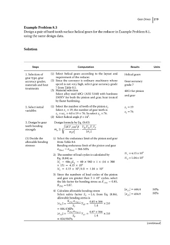
Example Problem 8.3                                             Gear Drives  219
                          Design a pair of hard tooth surface helical gears for the reducer in Example Problem 8.1,
                          using the same design data.


                          Solution


                               Steps                    Computation                   Results      Units
                           1. Selection of  (1) Select helical gears according to the layout and  Helical gears
                           gear type, gear  requirement of the reducer.
                           accuracy grades,  (2) Since the conveyor is ordinary machinery whose  Gear accuracy
                           materials and heat  speed is not very high, select gear accuracy grade  grade 7
                           treatments       7 from Table 8.5.
                                         (3) Material selection                    40Cr for pinion
                                            Select alloy steel 40Cr (AISI 5140) with hardness  and gear
                                            550HV for both the pinion and gear, heat treated
                                            by flame hardening.
                           2. Select initial  (1) Select the number of teeth of the pinion z 1  z = 19
                                                                                    1
                           variables        Select z = 19, thenumberofgearteeth is  z = 76
                                                 1
                                            z = uz = 4.0 × 19 = 76. So select z = 76.  2
                                             2   1                   2
                                                              ∘
                                         (2) Select helical angle    = 14 .
                           3. Design by gear  Design formula by Eq. (8.63)
                           teeth bending       √ 2KT cos     Y Y Y Y
                                                       2
                                                            Fa Sa      
                           strength        m ≥  3    1    ⋅
                                            n
                                                       z 2   [   ]
                                                     d 1       F
                           (1) Decide the  1) Select the endurance limit of the pinion and gear
                           allowable bending  from Table 8.6
                           stresses          Bending endurance limit of the pinion and gear
                                                 Flim1  =    Flim2  = 366 MPa
                                                                                   N = 4.15 × 10 9
                                           2) The number of load cycles is calculated by  1
                                             Eq. (8.84) as                         N = 1.04 × 10 9
                                                                                    2
                                             N =60n jL = 60 × 960 × 1 × (16 × 300
                                                      h
                                              1
                                                    1
                                             × 15) = 4.15 × 10 9
                                                         9
                                             N =4.15 × 10 ∕4.0=1.04 × 10 9
                                              2
                                           3) Since the numbers of load cycles of the pinion
                                                                    6
                                             and gear are greater than 3 × 10 cycles, select
                                             the life factor for bending stress as K  = 0.85,
                                                                       FN1
                                             K   = 0.87.
                                              FN2
                                                                                   [   ] = 444.4   MPa
                                           4) Calculate allowable bending stress    F1
                                             Select safety factor S = 1.4, from Eq. (8.86),  [   ] = 454.9  MPa
                                                             F                      F2
                                             allowable bending stress is
                                                   K FN1 F lim 1  0.85 × 366
                                                        
                                             [   ]=       Y ST  =      × 2.0
                                              F1
                                                     S F          1.4
                                             = 444.4 MPa
                                                   K           0.87 × 366
                                             [   ]=  FN2 F lim 2  Y  =  × 2.0
                                              F2     S     ST     1.4
                                             = 454.9MPa  F
                                                                                                (continued)
   236   237   238   239   240   241   242   243   244   245   246