
Page 231 - Analysis and Design of Machine Elements
P. 231
Gear Drives
is difference between the trial load factor K and K, the trial values of pitch diameter 209
t
d (or module m ) can be modified by
1t
nt
√
d = d 1t 3 K∕K t (8.88)
1
or
√
m = m nt 3 K∕K t (8.89)
n
The results from both strength analyses are compared and evaluated before the final
design decision can be made.
8.6.6.4 Geometrical Calculation
Because of the requirement of standardization and manufacturing process, variables
in gear transmission must be adjusted after the initial design. Basic rules are listed in
Table 8.7.
Variables in gear transmission are constrained by each other. On the one hand, they
have to meet the requirements listed in Table 8.7; on the other hand, they have to satisfy
geometrical constraints for proper meshing. A reasonable compromise between rele-
vant variables must be reached during design process.
For example, for a soft-tooth-surface helical gear in an enclosed gearing with a speed
ratio i = 3.243, assume the module is obtained by
√
2
2KT cos Y Y Y Y
Fa Sa
1
3
m ≥ 2 ⋅ = 2.31
n
z [ ]
F
d 1
Astandardmoduleisthenselectedas m n = 2.5 mm. Select z 1 = 24, then
∘
z = iz = 3.243 × 24 = 77.832, choose z = 78. Assuming = 15 , the centre distance is
2
2
1
m (z + z )
n
2
1
a = = 131.99
2cos
Round off the centre distance to 130 mm for the convenience of assembly and the helix
angleisconsequentlychanged to
m (z + z ) 2.5 ×(24 + 78) ∘
2
1
n
= arccos = arccos = 11.275
2a 2 × 130
∘ ∘
If is not within the range from 8 to 20 ,select z and z again and repeat this
1
2
calculation.
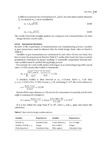
Table 8.7 Basic rules for design variable selection.
Variables Requirements Variables Requirements
Module m Standard value Centre distance a 0or5at digit
n
Number of teeth z , z Integer Face width b Integer
1 2
Pitch diameter d Calculated value Helix angle Calculated value