
Page 353 - Analysis and Design of Machine Elements
P. 353
4 3 Sliding Bearings 331
4
3 2 5
2 1 6
1
(a) (b)
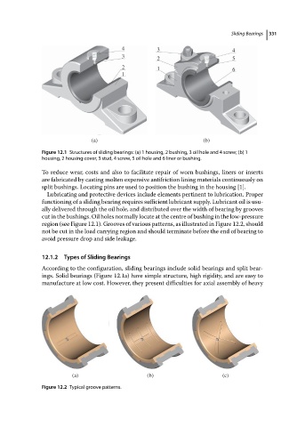
Figure 12.1 Structures of sliding bearings: (a) 1 housing, 2 bushing, 3 oil hole and 4 screw; (b) 1
housing, 2 housing cover, 3 stud, 4 screw, 5 oil hole and 6 liner or bushing.
To reduce wear, costs and also to facilitate repair of worn bushings, liners or inserts
are fabricated by casting molten expensive antifriction lining materials continuously on
split bushings. Locating pins are used to position the bushing in the housing [1].
Lubricating and protective devices include elements pertinent to lubrication. Proper
functioning of a sliding bearing requires sufficient lubricant supply. Lubricant oil is usu-
ally delivered through the oil hole, and distributed over the width of bearing by grooves
cut in the bushings. Oil holes normally locate at the centre of bushing in the low-pressure
region (see Figure 12.1). Grooves of various patterns, as illustrated in Figure 12.2, should
not be cut in the load carrying region and should terminate before the end of bearing to
avoid pressure drop and side leakage.
12.1.2 Types of Sliding Bearings
According to the configuration, sliding bearings include solid bearings and split bear-
ings. Solid bearings (Figure 12.1a) have simple structure, high rigidity, and are easy to
manufacture at low cost. However, they present difficulties for axial assembly of heavy
(a) (b) (c)
Figure 12.2 Typical groove patterns.