
Page 359 - Analysis and Design of Machine Elements
P. 359
Sliding Bearings
where is lubricant density. The densities for mineral oils are between 850 and 337
−3
900 kg m . The SI metric unit for kinematic viscosity is square metres per second
−1
−1
2
2
(m s ); while C.G.S unit is square centimetres per second (cm s ), called a stoke
(St), where 1 St = 100 cSt.
∘
The mean value of kinematic viscosity in centistokes (cSt) at 40 Ciscommonlyusedto
specifies oil viscosity grade number, which appear in ISO Standard 3448 and the Chinese
National Standard GB/T3141-1994. Twenty equivalent ISO/GB grades are specified,
∘
with kinematic viscosity values at 40 C of 2, 3, 5, 7, 10, 15, 22, 32, 46, 68, 100, 150, 220,
320, 460, 680, 1000, 1500, 2200 and 3200 cSt [8]. The viscosities defined by the American
Gear Manufacturers Association (AGMA) correlate its grades of 0∼8 with ISO viscosity
grades of 32∼680 [3]. The Society of Automotive Engineers (SAE) viscosity grades spec-
∘
∘
ify oil kinematic viscosity in centistokes at 100 C (212 F). Common grades are SAE 10,
20, 30, 40, 50, 60, 85, 90, 140 and 250 [3].
ISO VG 32 grade industrial oil, or an equivalent L-AN 32 or SAE 10 grade oils are
commonly used for general lubrication and for gear-type power transmissions in many
types of machinery, like automobiles, turbines, compressors, electric motors and various
other equipment [9].
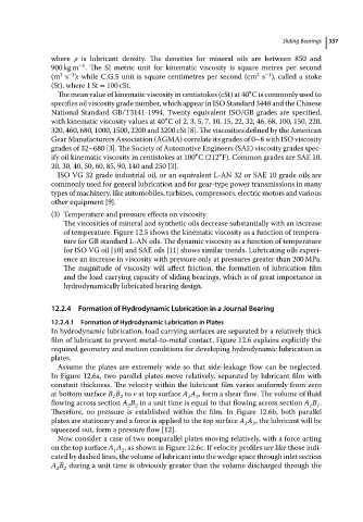
(3) Temperature and pressure effects on viscosity
The viscosities of mineral and synthetic oils decrease substantially with an increase
of temperature. Figure 12.5 shows the kinematic viscosity as a function of tempera-
ture for GB standard L-AN oils. The dynamic viscosity as a function of temperature
for ISO VG oil [10] and SAE oils [11] shows similar trends. Lubricating oils experi-
ence an increase in viscosity with pressure only at pressures greater than 200 MPa.
The magnitude of viscosity will affect friction, the formation of lubrication film
and the load carrying capacity of sliding bearings, which is of great importance in
hydrodynamically lubricated bearing design.
12.2.4 Formation of Hydrodynamic Lubrication in a Journal Bearing
12.2.4.1 Formation of Hydrodynamic Lubrication in Plates
In hydrodynamic lubrication, load carrying surfaces are separated by a relatively thick
film of lubricant to prevent metal-to-metal contact. Figure 12.6 explains explicitly the
required geometry and motion conditions for developing hydrodynamic lubrication in
plates.
Assume the plates are extremely wide so that side-leakage flow can be neglected.
In Figure 12.6a, two parallel plates move relatively, separated by lubricant film with
constant thickness. The velocity within the lubricant film varies uniformly from zero
at bottom surface B B to v at top surface A A , form a shear flow. The volume of fluid
1 2 1 2
flowing across section A B in a unit time is equal to that flowing across section A B .
2 2
1 1
Therefore, no pressure is established within the film. In Figure 12.6b, both parallel
plates are stationary and a force is applied to the top surface A A , the lubricant will be
1
2
squeezed out, form a pressure flow [12].
Now consider a case of two nonparallel plates moving relatively, with a force acting
on the top surface A A , as shown in Figure 12.6c. If velocity profiles are like those indi-
1 2
cated by dashed lines, the volume of lubricant into the wedge space through inlet section
A B during a unit time is obviously greater than the volume discharged through the
2 2