
Page 400 - Analysis and Design of Machine Elements
P. 400
Analysis and Design of Machine Elements
378
α = 30°~45° α = 2°~8°
α α α α
Figure 13.3 Teeth of jaw clutches.
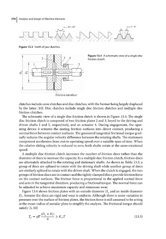
Figure 13.4 A schematic view of a single disc
2 3 4 friction clutch.
1 5
D o D i
Friction interface
clutches include cone clutches and disc clutches, with the former being largely displaced
by the latter [10]. Disc clutches include single disc friction clutches and multiple disc
friction clutches.
The schematic view of a single disc friction clutch is shown in Figure 13.4. The single
disc friction clutch is composed of two friction plates 2 and 3, keyed to the driving and
driven shafts 1 and 5, respectively, and an actuator 4. During engagement, the oper-
ating device 4 actuates the mating friction surfaces into direct contact, producing a
normal force between contact surfaces. The generated tangential frictional torque grad-
ually reduces the angular velocity difference between the rotating shafts. The stationary
component accelerates from rest to operating speed over a suitable span of time. When
the relative sliding velocity is reduced to zero, both shafts rotate at the same rotational
speed.
A multiple disc friction clutch increases the number of friction discs rather than the
diameter of discs to increase the capacity. In a multiple disc friction clutch, friction discs
are alternately attached to the rotating and stationary shafts. As shown in Table 13.3, a
group of discs are splined to rotate with the driving shaft while another group of discs
are similarly splined to rotate with the driven shaft. When the clutch is engaged, the two
groups of friction discs are in contact and the tightly clamped discs provide friction force
on the contact surfaces. The friction force is proportional to the applied normal force
and acts in the tangential direction, producing a frictional torque. The normal force can
be adjusted to achieve maximum capacity and minimum wear.
Figure 13.4 shows friction plates with an outside diameter D and an inside diameter
o
D . Assume the discs are rigid and wear is uniform. Although there is some variation in
i
pressure over the surface of friction plates, the friction force is still assumed to be acting
at the mean radius of annular plate to simplify the analysis. The frictional torque should
satisfy [5, 10]
(D + D )
o
i
T = zfF ≥ K T (13.3)
f
A
4