
Page 403 - Analysis and Design of Machine Elements
P. 403
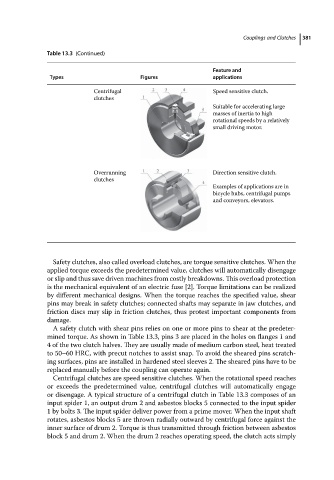
Table 13.3 (Continued)                                   Couplings and Clutches  381
                                                                          Feature and
                           Types                     Figures              applications

                                       Centrifugal                        Speed sensitive clutch.
                                       clutches
                                                                          Suitable for accelerating large
                                                                          masses of inertia to high
                                                                          rotational speeds by a relatively
                                                                          small driving motor.


                                       Overrunning                        Direction sensitive clutch.
                                       clutches
                                                                          Examples of applications are in
                                                                          bicycle hubs, centrifugal pumps
                                                                          and conveyors, elevators.


                            Safety clutches, also called overload clutches, are torque sensitive clutches. When the
                          applied torque exceeds the predetermined value, clutches will automatically disengage
                          or slip and thus save driven machines from costly breakdowns. This overload protection
                          is the mechanical equivalent of an electric fuse [2]. Torque limitations can be realized
                          by different mechanical designs. When the torque reaches the specified value, shear
                          pins may break in safety clutches; connected shafts may separate in jaw clutches, and
                          friction discs may slip in friction clutches, thus protest important components from
                          damage.
                            A safety clutch with shear pins relies on one or more pins to shear at the predeter-
                          mined torque. As shown in Table 13.3, pins 3 are placed in the holes on flanges 1 and
                          4 of the two clutch halves. They are usually made of medium carbon steel, heat treated
                          to 50–60 HRC, with precut notches to assist snap. To avoid the sheared pins scratch-
                          ing surfaces, pins are installed in hardened steel sleeves 2. The sheared pins have to be
                          replaced manually before the coupling can operate again.
                            Centrifugal clutches are speed sensitive clutches. When the rotational speed reaches
                          or exceeds the predetermined value, centrifugal clutches will automatically engage
                          or disengage. A typical structure of a centrifugal clutch in Table 13.3 composes of an
                          input spider 1, an output drum 2 and asbestos blocks 5 connected to the input spider
                          1 by bolts 3. The input spider deliver power from a prime mover. When the input shaft
                          rotates, asbestos blocks 5 are thrown radially outward by centrifugal force against the
                          inner surface of drum 2. Torque is thus transmitted through friction between asbestos
                          block 5 and drum 2. When the drum 2 reaches operating speed, the clutch acts simply