
Page 406 - Analysis and Design of Machine Elements
P. 406
Analysis and Design of Machine Elements
384
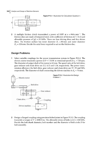
Figure P13.1 Illustration for Calculation Question 1.
−1
2 A multiple friction clutch transmitted a power of 5 kW at n = 960 r min .The
friction discs are made of tempered steel, with coefficient of friction of f = 0.15 and
allowable pressure of [p] = 0.3 MPa. There are four driving discs and five driven
discs. The friction surface has inner diameter D = 80 mm and outer diameter
i
D = 120 mm. Decide the axial force required to act on the friction disc.
o
Design Problems
1 Select suitable couplings for the power transmission system in Figure P13.2. The
electric motor transmits a power of P = 7.5 kW at rotational speed of n = 720 rpm.
1
The diameter of output shaft of the motor is 42 mm. The speed ratio of the belt drive,
gear reducer and chain drive are 2.2, 4.15 and 1.54, respectively. The power trans-
mission efficiency the belt drive, gear reducer and chain drive are 97, 99 and 96%,
respectively. The diameter of shaft connecting the driven machine is d = 70 mm.
2
Figure P13.2 Illustration for Design
Problem 1.
2 Design a flanged coupling using precision bolted joints in Figure P13.3. The coupling
transmits a torque of T = 2000 N m. The allowable stress of bolts is [ ] = 150 MPa.
Decide the bolt shank diameter, bolt number and the diameter of bolt circle D for
bolt assembly.