
Page 151 - Analysis, Synthesis and Design of Chemical Processes, Third Edition
P. 151
In order to determine the primary flow paths, we develop systems (by drawing envelopes around
equipment) that progressively include additional unit operations. Reference should be made to Figure
E5.2(a) for viewing and identifying systems for tracing hydrogen.
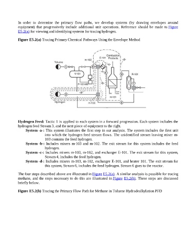
Figure E5.2(a) Tracing Primary Chemical Pathways Using the Envelope Method
Hydrogen Feed: Tactic 1 is applied to each system in a forward progression. Each system includes the
hydrogen feed Stream 3, and the next piece of equipment to the right.
System -a-: This system illustrates the first step in our analysis. The system includes the first unit
into which the hydrogen feed stream flows. The unidentified stream leaving mixer m-
103 contains the feed hydrogen.
System -b-: Includes mixers m-103 and m-102. The exit stream for this system includes the feed
hydrogen.
System -c-: Includes mixers m-103, m-102, and exchanger E-101. The exit stream for this system,
Stream 4, includes the feed hydrogen.
System -d-: Includes mixers m-103, m-102, exchanger E-101, and heater 101. The exit stream for
this system, Stream 6, includes the feed hydrogen. Stream 6 goes to the reactor.
The four steps described above are illustrated in Figure E5.2(a). A similar analysis is possible for tracing
methane, and the steps necessary to do this are illustrated in Figure E5.2(b). These steps are discussed
briefly below.
Figure E5.2(b) Tracing the Primary Flow Path for Methane in Toluene Hydrodealkylation PFD