
Page 150 - Analysis, Synthesis and Design of Chemical Processes, Third Edition
P. 150
The path for toluene was identified as an enhanced solid line in Example 5.1. For this case, it was not
necessary to apply any additional information about the unit operations to establish this path. The two
streams that joined the toluene path did not change the fact that all the feed toluene remained as part of the
stream. All the toluene fed to the process in Stream 1 entered the reactor, and this path represents the
primary path for toluene.
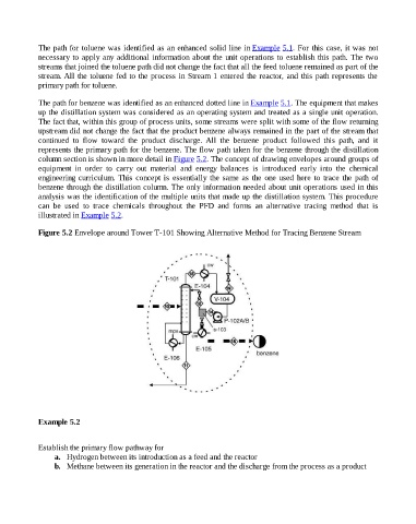
The path for benzene was identified as an enhanced dotted line in Example 5.1. The equipment that makes
up the distillation system was considered as an operating system and treated as a single unit operation.
The fact that, within this group of process units, some streams were split with some of the flow returning
upstream did not change the fact that the product benzene always remained in the part of the stream that
continued to flow toward the product discharge. All the benzene product followed this path, and it
represents the primary path for the benzene. The flow path taken for the benzene through the distillation
column section is shown in more detail in Figure 5.2. The concept of drawing envelopes around groups of
equipment in order to carry out material and energy balances is introduced early into the chemical
engineering curriculum. This concept is essentially the same as the one used here to trace the path of
benzene through the distillation column. The only information needed about unit operations used in this
analysis was the identification of the multiple units that made up the distillation system. This procedure
can be used to trace chemicals throughout the PFD and forms an alternative tracing method that is
illustrated in Example 5.2.
Figure 5.2 Envelope around Tower T-101 Showing Alternative Method for Tracing Benzene Stream
Example 5.2
Establish the primary flow pathway for
a. Hydrogen between its introduction as a feed and the reactor
b. Methane between its generation in the reactor and the discharge from the process as a product