
Page 421 - Analysis, Synthesis and Design of Chemical Processes, Third Edition
P. 421
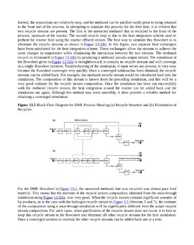
formed, the separations are relatively easy, and the methanol can be purified easily prior to being returned
                    to the front end of the process. In attempting to simulate this process for the first time, it is evident that
                    two recycle streams are present. The first is the unreacted methanol that is recycled to the front of the
                    process, upstream of the reactor. The second recycle loop is due to the heat integration scheme used to
                    preheat the reactor feed using the reactor effluent stream. The best way to simulate this flowsheet is to
                    eliminate  the  recycle  streams  as  shown  in Figure 13.5(b). In this figure, two separate heat exchangers
                    have been substituted for the heat integration scheme. These exchangers allow the streams to achieve the
                    same changes in temperature while eliminating the interaction between the two streams. The methanol
                    recycle is eliminated in Figure 13.5(b) by producing a methanol pseudo-output stream. The simulation of
                    the flowsheet given in Figure 13.5(b) is straightforward; it contains no recycle streams and will converge

                    in a single flowsheet iteration. Troubleshooting of the simulation, if input errors are present, is very easy
                    because the flowsheet converges very quickly. Once a converged solution has been obtained, the recycle
                    streams can be added back. For example, the methanol recycle stream would be introduced back into the
                    simulation. The composition of this stream is known from the preceding simulation, and this will be a
                    very good estimate for the recycle stream composition. Once the simulation has been run successfully
                    with  the  methanol  recycle  stream,  the  heat  integration  around  the  reactor  can  be  added  back  and  the
                    simulation  run  again. Although this method may seem unwieldy, it does provide a reliable method for
                    obtaining a converged simulation.


                    Figure 13.5 Block Flow Diagram for DME Process Showing (a) Recycle Structure and (b) Elimination of
                    Recycles


                    For the DME flowsheet in Figure 13.5, the unreacted methanol that was recycled was almost pure feed
                    material. This means that the estimate of the recycle stream composition, obtained from the once-through
                    simulation using Figure 13.5(b), was very good. When the recycle stream contains significant amounts of
                    by-products, as is the case with the hydrogen recycle stream in Figure 1.5 (Streams 5 and 7), the estimate
                    of the composition using a once-through simulation will be significantly different from the actual recycle
                    stream composition. For such cases, when purification of the recycle stream does not occur, it is best to
                    keep this recycle stream in the flowsheet and eliminate all other recycle streams for the first simulation.
                    Once a converged solution is reached, the other recycle streams can be added back one at a time.