
Page 251 - Anatomy of a Robot
P. 251
09_200256_CH09/Bergren 4/17/03 11:24 AM Page 236
236 CHAPTER NINE
approach the Shannon limit. As might be expected, more efficient modulators are more
expensive. Most people settle for wasting bandwidth rather than paying for a more
expensive modulator.
COMPLICATED MODULATORS
These previous examples are very rudimentary modulation schemes. Often, in modern
modulation methods, more than one carrier parameter is modulated at the same time.
Let’s also introduce here the concept of a symbol. A symbol is simply a multiple bit
number used for modulation. A byte could be an 8-bit symbol used in ASK to set the
amplitude to one of 256 different levels. The process of modulating the carrier by a sym-
bol changes the character of the carrier waveforms.
The receiver demodulates the data and makes an attempt to determine the character
of the waveform in order to classify which symbol it represents. The demodulator in the
receiver serves to quantify the received waveform into a symbol space. Visualize the
symbol space as a multidimensional data space within which the received signal is mov-
ing. As the amplitude, frequency, and phase of the received signal change, the signal
moves around in the receiver’s symbol space. If, for instance, 256 different symbols are
defined, then 256 different points are in the symbol space where these symbols reside.
If the received signal is crossing one of these 256 points when the data clock ticks, the
received symbol associated with that point is chosen as the received symbol, and the
data (8 bits) represented by that symbol is dumped into the receiver’s output.
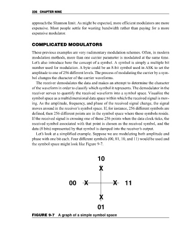
Let’s look at a simplified example. Suppose we are modulating both amplitude and
phase with one bit each. Four different symbols (00, 01, 10, and 11) would be used and
the symbol space might look like Figure 9-7.
10
X
00 X X 11
X
01
FIGURE 9-7 A graph of a simple symbol space