
Page 66 - Anatomy of a Robot
P. 66
02_200256_CH02/Bergren 4/17/03 11:23 AM Page 51
CONTROL SYSTEMS 51
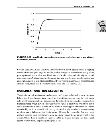
FIGURE 2-20 A critically damped second-order control system is sometimes
considered optimal.
become nonlinear. In this situation, the second-order model breaks down, the spring
constant becomes quite large for a while, and all bumps are transmitted directly to the
passengers and the rest of the car. That’s how you bend the rims, ruin the alignment, and
get a neck cramp! It is up to us, as designers, to make sure the second-order system has
enough headroom to avoid these problems. If your robot is to carry eggs home from the
chicken coop, make sure the suspension is a good one (see Figure 2-21).
NONLINEAR CONTROL ELEMENTS
Thus far in our calculations and mathematics, we’ve assumed that all control elements
behave in a linear fashion. Very roughly defined, this assumes a smooth, continuous
action with no jerky motions. Bringing in a definition from calculus, this linear motion
is characterized by curves with finite derivatives. Figure 2-22 shows a continuous curve
and a discontinuous curve. Picture for the moment sending your robot over the terrain
described by each curve and it will be easy to visualize why we should be considering
nonlinear control elements in this discussion. We must be prepared to deal with such
matters because most robots have some nonlinear elements somewhere within the
design. Often, these elements are inherent in the mechanics or creep into the control
system when we least expect it (see Figure 2-22).