
Page 63 - Anatomy of a Robot
P. 63
02_200256_CH02/Bergren 4/17/03 11:23 AM Page 48
48 CHAPTER TWO
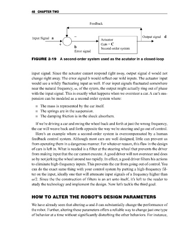
_ Feedback
Input Signal a Actuator Output signal d
+ Gain = C
b
Second-order system
Error signal
FIGURE 2-19 A second-order system used as the acutator in a closed-loop
input signal. Since the actuator cannot respond right away, output signal d would not
change right away. The error signal b would reflect our wild inputs. The actuator input
would see a wildly fluctuating input as well. If our input signals fluctuated somewhere
near the natural frequency, v, of the sytem, the output might actually ring out of phase
with the input signal. This is exactly what happens when we oversteer a car. A car’s sus-
pension can be modeled as a second order system where:
The mass is represented by the car itself.
The springs are in the suspension.
The damping friction is in the shock absorbers.
If we’re driving a car and swing the wheel back and forth at just the wrong frequency,
the car will weave back and forth opposite the way we’re steering and go out of control.
Here’s an example where a second-order system is overcompensated by a human
feedback control system. Although most cars are well designed, little can prevent us
from operating them in a dangerous manner. For whatever reason, this flaw in the design
of cars is left in. What is needed is a filter at the steering wheel that prevents the driver
from making input that the car cannot execute. A good driver will not oversteer and does
so by not jerking the wheel around too rapidly. In effect, a good driver filters his actions
to eliminate high-frequency inputs. This prevents the car from going out of control. You
can do the exact same thing with your control system by putting a high-frequency fil-
ter on the input, ideally one that will attenuate input signals of a frequency higher than
v/2. Since the the construction of filters is an art unto itself, it’s left to the reader to
study the technology and implement the design. Now let’s tackle the third goal.
HOW TO ALTER THE ROBOT’S DESIGN PARAMETERS
We have already seen that altering v and d can substantially change the performance of
the robot. Further, altering these parameters offers a reliable way to change just one type
of behavior at a time without significantly disturbing the other behaviors. For instance,