
Page 100 - Antennas for Base Stations in Wireless Communications
P. 100
Base Station Antennas for Mobile Radio Systems 73
The advent of 2G systems with their digital signal formats led to
the universal adoption of higher levels of control of antenna elevation
sidelobes and the general use of beamtilt to optimize network capacity.
When new networks commence operation, they are generally coverage-
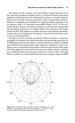
limited, so antennas are installed with small beamtilts, typically 2° for
an antenna with a 5° elevation beamwidth (Figure 2.15). As the net-
works became denser, it became necessary to increase the mechanical
tilt of existing antennas or to replace them with antennas with larger
electrical tilts. This process was labor intensive and required manufac-
turers and network operators to maintain inventories of antennas with
a variety of electrical tilts.
The advent of 3G networks provided a further incentive to optimize
beamtilts to a higher level of precision than was previously necessary. In
a CDMA network, all users share a common frequency and their signals
are identified and separated by code sequences assigned to each user.
When users are located between cells, or between the sectors of the same
cell, their signals are received by more than one cell (or sector), and they
are combined together by processes known as soft (or softer) handoff.
When a mobile is in soft handoff between cells, it enjoys improved BER
0°
330° 30°
300° 60°
270° 90°
240° 120°
210° 150°
180°
Figure 2.15 Constant field strength azimuth footprint for a 65°
antenna with electrical tilts of 0° (outermost), 2°, 5°, and 8°, assum-
ing well-controlled elevation patterns and flat terrain