
Page 102 - Antennas for Base Stations in Wireless Communications
P. 102
Base Station Antennas for Mobile Radio Systems 75
Top of array
Phase
Required additional phase front Bottom
0 −f −2f −3f −4f −5f −6f −7f
Figure 2.16 An 8l array with linear variable phase shift
In Figure 2.17 adjacent elements are provided with a common fixed
phase difference, and variable phase is applied between the pairs of
elements. The phase shifters are designed as tapped transmission
lines—this design method has the advantage that a movement of the
tap position over a length of line y° long provides a relative phase
advance between outputs of +y° when the tap is at one end of its travel
and of −y° when at the other end, a relative total of 2y°. If the tapped
lines are arranged in circular arcs, the maximum phase shift for a given
angular movement of the input shaft can be adjusted by choosing the
appropriate radius. Because the phases of the elements at each end of
the array move symmetrically about zero, an additional pair of elements
with fixed (0°) phase can be introduced at the center of the array. This
allows a 10l array to be driven with only two phase shifters, which can
be nested concentrically to provide a compact mechanical construction.
An identical arrangement is needed for each polarization, and in a mul-
tiband antenna, separate feed networks and variable phase shifters are
required for each frequency band.
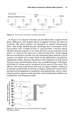
Identical pairs of radiating elements with fixed relative phases Radius r Power division
network
Input
Radius 2r
Figure 2.17 Feed network for a 10l array using two tapped-
line phase shifters