
Page 166 -
P. 166
134 Part II Gas Drilling Systems
Substituting Eqs. (6.42) and (6.45) into Eq. (6.41) and rearranging the
latter yields
v go A r ffiffiffiffiffiffiffiffiffiffiffiffiffiffiffiffiffiffiffi
Q go = P (6.46)
4:84 23:41S g T
Since this equation still involves in situ pressure P,itmustbecombined
with Eq. (6.18) to solve the minimum required gas flow rate Q go .This
approach can be used to generate engineering charts for various well con-
ditions. Some of the charts are presented in Appendix B.
The results of Illustrative Examples 6.1 and 6.2 indicate that the cal-
culated minimum required air injection rate given by the minimum velo-
city criterion is slightly lower than that given by the minimum kinetic
energy criterion, even though a very large particle size (nearly ¼ inch) is
used. Although the minimum velocity criterion appears to be more gen-
eral, difficulties associated with the rough estimation of the unknown
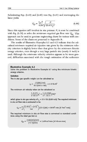
Illustrative Example 6.2
Solve the problem in Illustrative Example 6.1 using the minimum kinetic
energy criterion.
Solution
The in situ gas specific weight can be calculated as
γ = ð1Þð85Þð144Þ = 0:37 lb/ft 3
g
53:3ð460 + 160Þ
The minimum air velocity value can be calculated as
1 0:37 v = 1 0:0765 2
2
2 32:2 g 2 32:2 ð50Þ
which gives in situ gas velocity of v g = 22:6 ft/s [6.58 m/s]. The required minimum
in situ air flow rate is estimated to be
2 2
Q g = π ð7:875Þ − ð4:5Þ 3 3
4 144 ð22:6Þð60Þ = 309 ft /min ½8:76m /min
The required minimum in situ air flow rate is converted to standard condi-
tions using the ideal gas law as
Q go = ð520Þð85Þð309Þ = 1,499 scf/min ½42:48 scm/min
ð14:7Þð620Þ