
Page 61 -
P. 61
Mud Hydraulics Fundamentals 37
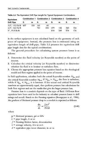
Table 2.2 The Equivalent Drill Pipe Length for Typical Equipment Combinations
Combination 1 Combination 2 Combination 3 Combination 4
Equivalent
Drill Pipe ft m ft m ft m ft m
3.5″, 13.3 lb/ft 437 133 161 49
4.5″, 16.6 lb/ft 761 232 479 146 340 104
5″, 19.5 lb/ft 816 249 576 176
in the surface equipment is not calculated based on the geometry of each
piece of equipment. Instead, the pressure loss is estimated using an
equivalent length of drill pipe. Table 2.2 presents the equivalent drill
pipe length data for the typical combinations.
The general procedure for calculating system pressure losses is as
follows:
1. Determine the fluid velocity (or Reynolds number) at the point of
interest.
2. Calculate the critical velocity (or Reynolds number) to determine
whether the fluid is in laminar or turbulent flow.
3. Choose the appropriate pressure loss equation based on the rheological
model and flow regime applied to the point of interest.
In field applications, calculate both the actual Reynolds number N Re and
the critical Reynolds number N Rec .If N Re > N Rec , the flow is turbulent,
while if N Re < N Rec , it is laminar. If the actual and critical Reynolds
numbers are approximately equal, then perform pressure loss calculations for
both flow regimes and use the results that give the larger pressure loss.
Pressure loss in a conduit depends on the type of fluid. Different flow
equations have been used in the industry to calculate pressure losses in drill
strings and annuli. Based on the Fanning equation (Bourgoyne et al., 1986),
the gradient of frictional pressure drop in a conduit is expressed as follows:
f ρ v 2
dp f f
= (2.48)
dL 25:8d
where
p f = frictional pressure, psi or kPa
L = pipe length, ft or m
f = Fanning friction factor, dimensionless
v = average velocity, ft/s or m/s
d = equivalent pipe inner diameter, in or m