
Page 86 -
P. 86
Mud Pumps 63
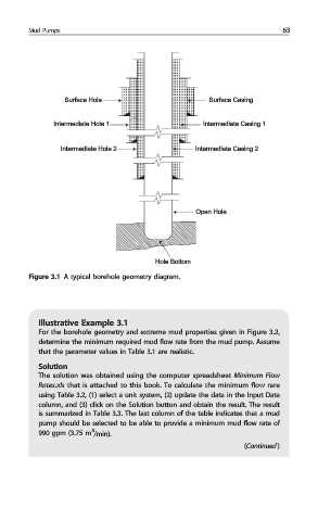
Surface Hole Surface Casing
Intermediate Hole 1 Intermediate Casing 1
Intermediate Hole 2 Intermediate Casing 2
Open Hole
Hole Bottom
Figure 3.1 A typical borehole geometry diagram.
Illustrative Example 3.1
For the borehole geometry and extreme mud properties given in Figure 3.2,
determine the minimum required mud flow rate from the mud pump. Assume
that the parameter values in Table 3.1 are realistic.
Solution
The solution was obtained using the computer spreadsheet Minimum Flow
Rates.xls that is attached to this book. To calculate the minimum flow rare
using Table 3.2, (1) select a unit system, (2) update the data in the Input Data
column, and (3) click on the Solution button and obtain the result. The result
is summarized in Table 3.3. The last column of the table indicates that a mud
pump should be selected to be able to provide a minimum mud flow rate of
3
990 gpm (3.75 m /min).
(Continued )