
Page 90 -
P. 90
66 Part I Liquid Drilling Systems
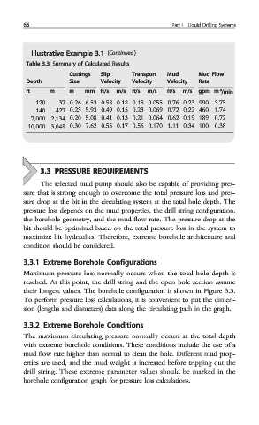
Illustrative Example 3.1 (Continued )
Table 3.3 Summary of Calculated Results
Cuttings Slip Transport Mud Mud Flow
Depth Size Velocity Velocity Velocity Rate
3
ft m in mm ft/s m/s ft/s m/s ft/s m/s gpm m /min
120 37 0.26 6.53 0.58 0.18 0.18 0.055 0.76 0.23 990 3.75
140 427 0.23 5.93 0.49 0.15 0.23 0.069 0.72 0.22 460 1.74
7,000 2,134 0.20 5.08 0.41 0.13 0.21 0.064 0.62 0.19 189 0.72
10,000 3,048 0.30 7.62 0.55 0.17 0.56 0.170 1.11 0.34 100 0.38
3.3 PRESSURE REQUIREMENTS
The selected mud pump should also be capable of providing pres-
sure that is strong enough to overcome the total pressure loss and pres-
sure drop at the bit in the circulating system at the total hole depth. The
pressure loss depends on the mud properties, the drill string configuration,
the borehole geometry, and the mud flow rate. The pressure drop at the
bit should be optimized based on the total pressure loss in the system to
maximize bit hydraulics. Therefore, extreme borehole architecture and
condition should be considered.
3.3.1 Extreme Borehole Configurations
Maximum pressure loss normally occurs when the total hole depth is
reached. At this point, the drill string and the open hole section assume
their longest values. The borehole configuration is shown in Figure 3.3.
To perform pressure loss calculations, it is convenient to put the dimen-
sion (lengths and diameters) data along the circulating path in the graph.
3.3.2 Extreme Borehole Conditions
The maximum circulating pressure normally occurs at the total depth
with extreme borehole conditions. These conditions include the use of a
mud flow rate higher than normal to clean the hole. Different mud prop-
erties are used, and the mud weight is increased before tripping out the
drill string. These extreme parameter values should be marked in the
borehole configuration graph for pressure loss calculations.