
Page 31 - Applied Petroleum Geomechanics
P. 31
Stresses and strains 21
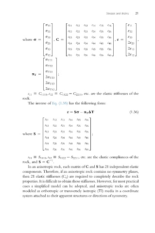
2 3 2 3 2 3
s 11 c 11 c 12 c 13 c 14 c 15 c 16 ε 11
c
6 7 6 7 6 ε 7
6 12 c 22 c 23 c 24 c 25
6 s 22 7 c 26 7 6 22 7
6 7 6 7 6 7
6 s 33 7 6 c 13 c 23 c 33 c 34 c 35 c 36 7 6 ε 33 7
where s ¼ 6 7 , C ¼ 6 7 , ε ¼ 6 7 ,
6 7 6 c 7 6 7
6 14 c 24 c 34 c 44 c 45 c 46 7 2ε 23 7
6 6
s 23 7
6 7 6 7 6 7
4 s 13 5 4 c 15 c 25 c 35 c 45 c 55 c 56 5 4 2ε 13 5
s 12 c 16 c 26 c 36 c 46 c 56 c 66 2ε 12
2 3
a T11
6 7
6 a T22 7
6 7
6 a T33 7
a T ¼ 6 7 ;
6 7
6 2a T23 7
6 7
4 2a T13 5
2a T12
c 11 h C 1111 , c 12 h C 1122 ¼ C 2211 , etc. are the elastic stiffnesses of the
rock.
The inverse of Eq. (1.35) has the following form:
ε ¼ Ss a T DT (1.36)
2 3
s 11 s 12 s 13 s 14 s 15 s 16
s 7
6 12 s 22 s 23 s 24 s 25 s 26 7
6
6 7
6 s 13 s 23 s 33 s 34 s 35 s 36 7
where S ¼ 6 7 ;
6 s 7
6 14 s 24 s 34 s 44 s 45 s 46 7
6 7
4 s 15 s 25 s 35 s 45 s 55 s 56 5
s 16 s 26 s 36 s 46 s 56 s 66
s 11 h S 1111 , s 12 h S 1122 ¼ S 2211 , etc. are the elastic compliances of the
1
rock, and S ¼ C .
In an anisotropic rock, each matrix of C and S has 21 independent elastic
components. Therefore, if an anisotropic rock contains no symmetry planes,
then 21 elastic stiffnesses (C ij ) are required to completely describe the rock
properties. It is difficult to obtain those stiffnesses. However, for most practical
cases a simplified model can be adopted, and anisotropic rocks are often
modeled as orthotropic or transversely isotropic (TI) media in a coordinate
system attached to their apparent structures or directions of symmetry.