
Page 78 - APPLIED PROCESS DESIGN FOR CHEMICAL AND PETROCHEMICAL PLANTS, Volume 1, 3rd Edition
P. 78
-
64 Applied Process Design for Chemical and Petrochemical Plants IPS
TUBE OD
-K
i I INDICATES SIZE INDICATES
NOMINAL
OUISIDE
DIAMETER
DIAMETER
AE-
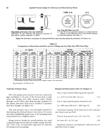
.Ir How Tube OD Differs from IPS
Dependable performance; fast, easy installation In Tube OD the size specified indicates its outside diameter
Uniformity of wall thickness and geometric accuracy of . . . whereas in Iron Pipe Size (I P S 1, the size has reference
ends permit precise alignment of joints. to a nominal diameter. See Table 2-1.
Figure 2-9. Dimension comparison of tubing and IPS (iron pipe size) steel piping. By permission, Tri-Clover, Inc.
Table 2-1
Comparison of dimensions and flow area for Tubing and Iron Pipe Size (IPS) Steel Pipe.
'Bawd on wet) s%k&nsn lkw on tollowlng p.oar.
*'tndl~a wrt.r lmintd. in deeting IIM size wi%h ~.p.fity dolst to @ow muinnnmt.
By permission Tri-Clover, Inc.
Total Line Pressure Drop Background Information (Also see Chapter 3)
Gas or vapor density following perfect gas law:
The total piping system pressure drop for a particular
pipe installation is the sum of the friction drop in pipe p = 144 P' (T) (1544/MW), lbs/cu ft (2-5)
valves and fittings, plus other pressure losses (drops)
through control valves, plus drop through equipment in Gas or vapor specific gravity referred to air:
the system, plus static drop due to elevation or pressure
level. For example, see Figure 2-2. S, = MW of gas/MW of air = MW of gas/29 (2-6)
This total pressure loss is not necessarily required in Conversion between fluid head loss in feet and pres-
determining the fictional losses in the system. It is neces- sure drop in psi, any fluid:
sary when establishing gravity flow or the pumping head
requirements for a complete system. Pressure drop, pounds/sq in., AP = hLp/144 (2-7)
Design practice breaks the overall problem into small For water, AP = hL/2.31, psi (2-8)
component parts which allow for simple analysis and solu-
tion. This is the recommended approach for selection Equivalent diameter and hydraulic radius for non-cir-
and sizing of process piping. cular flow ducts or pipes