
Page 73 - APPLIED PROCESS DESIGN FOR CHEMICAL AND PETROCHEMICAL PLANTS, Volume 1, 3rd Edition
P. 73
Fluid Flow 59
Usual Industry Pipe Sizes and Glasses Practice the corrosion rate over a five-year life required 0.125
in. (%in.), then the 0.200 in. + 0.125 in. = 0.325 in.
Certain nominal process and utility pipe sizes are and the Schedule 40 pipe would not be strong enough
not in common use and hence their availability is lim- at the end of five years. Often the corrosion is calcu-
ited. Those not usually used are: % in., 1% in., 2% in., 3% lated for 10- or 15-years’ life before replacement. Cur-
in., 5 in., 22 in., 26 in., 32 in., 34 in. rently Schedule 80, 3411. pipe has a 0.300 in. wall
Some of the larger sizes, 22 in. and up, are used for spe- thickness, so even this is not good enough in carbon
cial situations. Also, some of the non-standard process steel. Rather than use the much heavier Schedule 160,
sizes such as 2% in., 3% in. and 5 in. are used by “packaged” the designer should reconsider the materials of con-
equipment siilppliers to connect components in their sys- struction as well as re-examine the corrosion data to
tem for use in processes such as refrigeration, drying, or be certain there is not unreasonable conservatism.
contacting. Perhaps stainless steel pipe or a “‘lined” pipe would
The most common schedule in use is 40, and it is use- give adequate strength and corrosion resistance. For a
ful for a wide range of pressures defined by ANSI Std. B bad corrosion condition, lined pipe using linings of
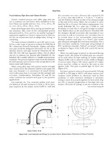
36.1 (American National Standards). Lighter wall thick- PVC (polyvinyl chloride), Teflon@’, or Saran@ typically
ness pipe would be designated Schedules 10, 20, or 30; as shown in Figure 2-5A, 2-5B, 2-5C and 2-5D can be
whereas, heavier wall pipe would be Schedules 60, 80, helpful.
100, 120, 140, 160 (see Appendix Table). Not all sched- While threaded pipe is joined by threaded fittings
ules are in common use, because after Schedule 40, the (Figure 2-4A), the joints of welded pipe are connect-
Schedule 80 is usually sufficient to handle most pressure ed to each other by butt welding or socket welding
situations. The process engineer must check this schedule (Figure 2-4B) and to valves by socket welds or flanges
f~r both pressure and corrosion to be certain there is suf- of several types (Figure 2-6) using a gasket of compo-
ficient metal wall thickness. sition material, rubber or metal at the joint to seal
When using alloy pipe with greater tensile strength against leaks. The joint is pulled tight by bolts (see
than carbon steel, the schedule numbers still apply, but Figure 2-7).
may vary, because it is unnecessary to install thicker For lower pressure systems of ap roximately 150 psig
walled alloy pipe than is necessary for the strength and at 400°F or 225 psig at IQOT, and where sanitary pre-
corrosion considerations. Schedules 10 and 20 are cautions (food products or chemicals used in food
rather common for stainless steel pipe in low pressure products) or some corrosion resistance is necessary,
applications. tubing is used. It is joined together by butt welds (Fig-
For example, for %in. nominal carbon steel pipe, ure 2-8) or special compression or hub-type end con-
the Schedule 40 wall thickness is 0.216 in. If the pres- nectors. This style of “piping” is not too common in the
sure required in the system needs 0.200 in. wall and (text continued on page 62)
r
-- -7
r
-
I
I
A
L---A”
igure 2-M. Lined-steel pipe and fittings for corrosive service. By permission, Performance Plastics Products.