Page 71 - APPLIED PROCESS DESIGN FOR CHEMICAL AND PETROCHEMICAL PLANTS, Volume 1, 3rd Edition
P. 71

Fluid Flow                                            57


                                                                           T               7
                                                                           4               i


                                                                 I--64           c---B---l
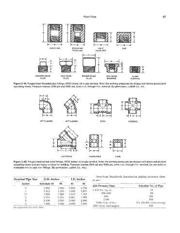
                                   COUPLING       RE DUCl NG        HALF            CAP
                                                  COUPLING        COUPLING


                         SQUARE HEAD       HEX HEAD      ROUND HEAD       HEX HEAD         FLUSH
                             PLUG           PLUG            PLUG          BUSHING         BUSHING
           Figure 2-4A. Forged steed threaded pipe fittings, WOG (water, oil or gas service). Note: the working pressures are always well above actual plant
           operaUing levels. Pressure classes 3000 psi and 6000 psi, sizes % in. through 4 in. nominal. By permission, Ladish CO., Inc.


                                                 P  C


                             90'  ELBOWS      450 E LBOWS            TEES                GROSSES


                                                                     T
                                                                     1               -f-


                                           LATERALS           COUPLINGS         CAPS
           Figure 2-48. Forged steel socket weld fittings, WOG (water, oil or gas service). Note: the working pressures are always well above actual plant
          operating levels and are heavy to allow for welding. Pressure classes 3000 psi and 6000 psi, sizes % in. through 4 in. nominal. Do not weld on
          malleable iron or cast iron fittings. (By permission, Ladish Go., lnc.)

                                                                   American Standards Association piping pressure class-
          Nominal Pipe Size      .D. Inches       I.D. Inches   es are:
                Inches      Schedule40    80     40      80                                                      __
                                                                MA Pressure Class               ~     c  No. of  ~Pipe   e  ~   ~     ~
                  %            1.050     1.050   0.824   0.742
                  1            1.313     1.315   1.049   0.957   I250 lbs./sq.  in.                     40
                  1%           1 .900    1.900   1.610   1.500        300-600                           80
                  2            2.375     '2.375   2.067   1.939         900                            120
                  3            3.500     3.500   3.068   2.900          1500                           160
                                                                   2500 (X in.4 in.)
          _       4  _     -  ~ 4.500    4.500   4.026   3.826   2500 (8 in. and larger)      XX  (double extra strong)
                                                                                                       160
          See Appendix for other sizes.                                                     ____.
   66   67   68   69   70   71   72   73   74   75   76